DFD6361-Maintenance.pdf - 第644页
F-74 3-2. Repla cing the Waterproof Cover/O -ring/V-ring for θ -axis Operation flow The procedure for replaci ng the waterproof cover, O-rin g and V-ring for θ - axis consists of the follo wing steps. 3-2-1 Removing the …
F-73
3-1-3. Completion of replacing the bellows
Procedures for completion of replacing the bellows
WARNING
- If you operate the machine while its interior and floor are wet with
water, you may receive an electric shock that could result in serious
injury or death.
If the machine gets wet with water, do not switch on the facility
power supply until the wetted areas dry up. Likewise, if the floor
gets wet with water, switch off the facility power supply and wipe the
floor until it is entirely dry.
- Upon the completion of replacement, operate the machine to verify
there is no water leakage. If water leakage occurs, shut off the
facility power supply and turn OFF the machine. And then properly
reinstall the bellows.
If you operate the machine while the machine interior or floor is wet
with water, you may receive electric shock that could result in
serious injury or death.
Step No. Do This
(Continued from the previous section)
1
Make sure that there is no water leakage inside the machine.
2
Close the splash cover and front arm section cover.
3
Turn ON the facility power source.
4
Open the facility main valves of the supply lines for the air,
wheel coolant water and spindle coolant water.
5
Open the circuit breaker lever lockout and turn ON the circuit
breaker.
6
Insert the key into the main switch and turn ON the main switch.
7
Press the <System Initial> button to effect system initialization.
8
Conduct dummy cutting for 30 minutes.
- Check for water leakage at the bellows mounting section.
- When there is any water leakage;
Repeat the steps 3-1-1 through 3-1-2 of this chapter.
F-74
3-2. Replacing the Waterproof Cover/O-ring/V-ring for
θ-axis
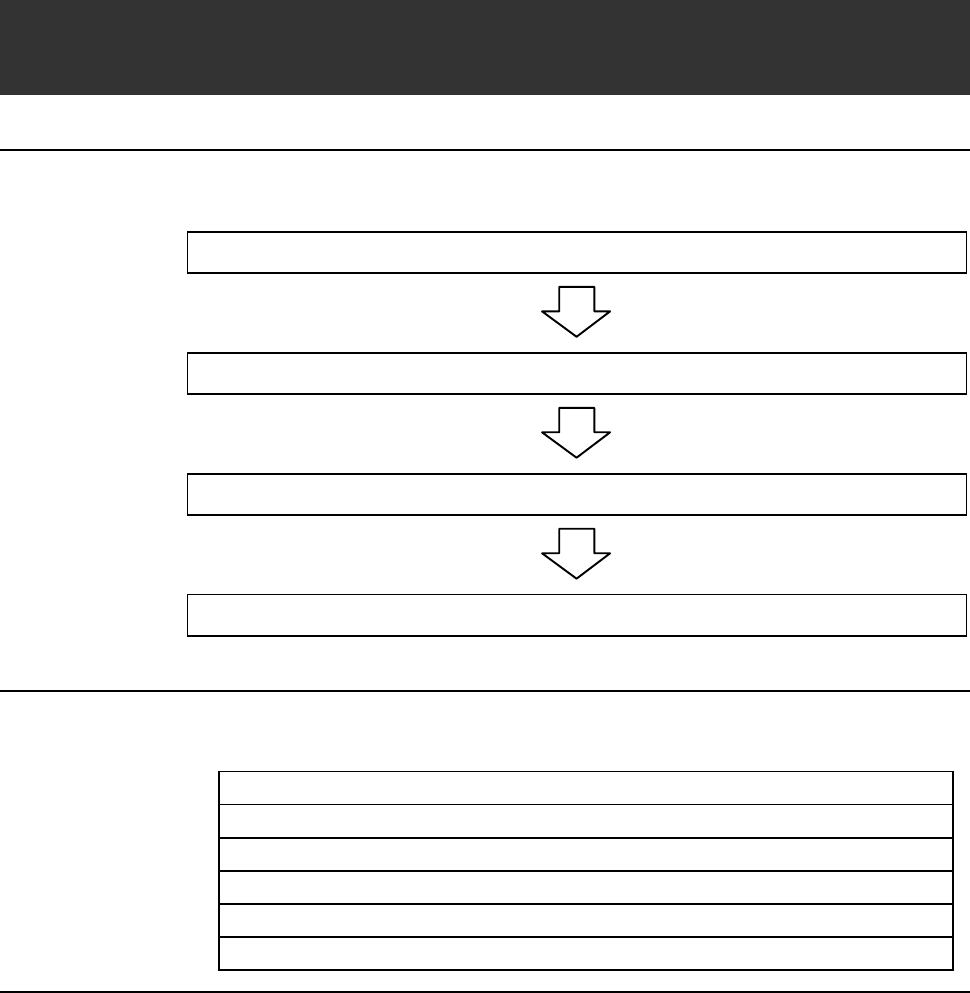
Operation flow
The procedure for replacing the waterproof cover, O-ring and V-ring for θ-
axis consists of the following steps.
3-2-1 Removing the chuck table
3-2-2 Removing the frame clump
3-2-3 Replacing the waterproof cover/O-ring/V-ring
3-2-4 Completion of replacing the waterproof cover/O-ring/V-ring
Before replacement
Have on hand the following items for replacing the waterproof cover, O-ring
and V-ring.
Alcohol
Lint-free cloth
Protective gloves
2.5mm Allen wrench
3mm Allen wrench (for removing the frame clump of DFD6351)
Phillips screwdriver
F-75
3-2-1. Removing the chuck table
Procedures for removing the chuck table
WARNING
- When you perform the procedure set forth in this section, you have
to place your hands in a drive section. If you perform maintenance
with the power ON, your fingers or hands may be caught or cut off.
Turn OFF the machine and shut off the facility power supply before
starting this procedure.
Also, ensure that no other person touches the machine during
operation.
- Your fingers could be cut or otherwise injured by broken workpiece.
When you remove broken workpiece or clean the working area, use
tweezers and do not remain barehanded.
- Performing maintenance while the machine or floor is wet with
water will cause electric shock hazard which may result in serious
injury or death.
Make sure that there is no water in the water case or bellows
section.
Step No. Do This
1
From outside of the splash cover, visually make sure that the
spindle is completely stopped.
2
Make sure that there is no water in the water case.
If there is any water in the water case, allow it to thoroughly dry.
Also, water in the bellows section must be wiped away with a
lint-free cloth.
3
Remove the chuck table.
- For the chuck table removal procedure;
See the section B-1, [Chuck Table Replacement].
Continued in the next section.