DFD6361-Maintenance.pdf - 第65页
A-49 4-2. Machine Protection Summary of this sectio n For the purpose of machine protection, the machine incorporates the interlocks for supply pressure of air and clean air pressure, fl ow rate of wheel and s pindle coo…
A-48
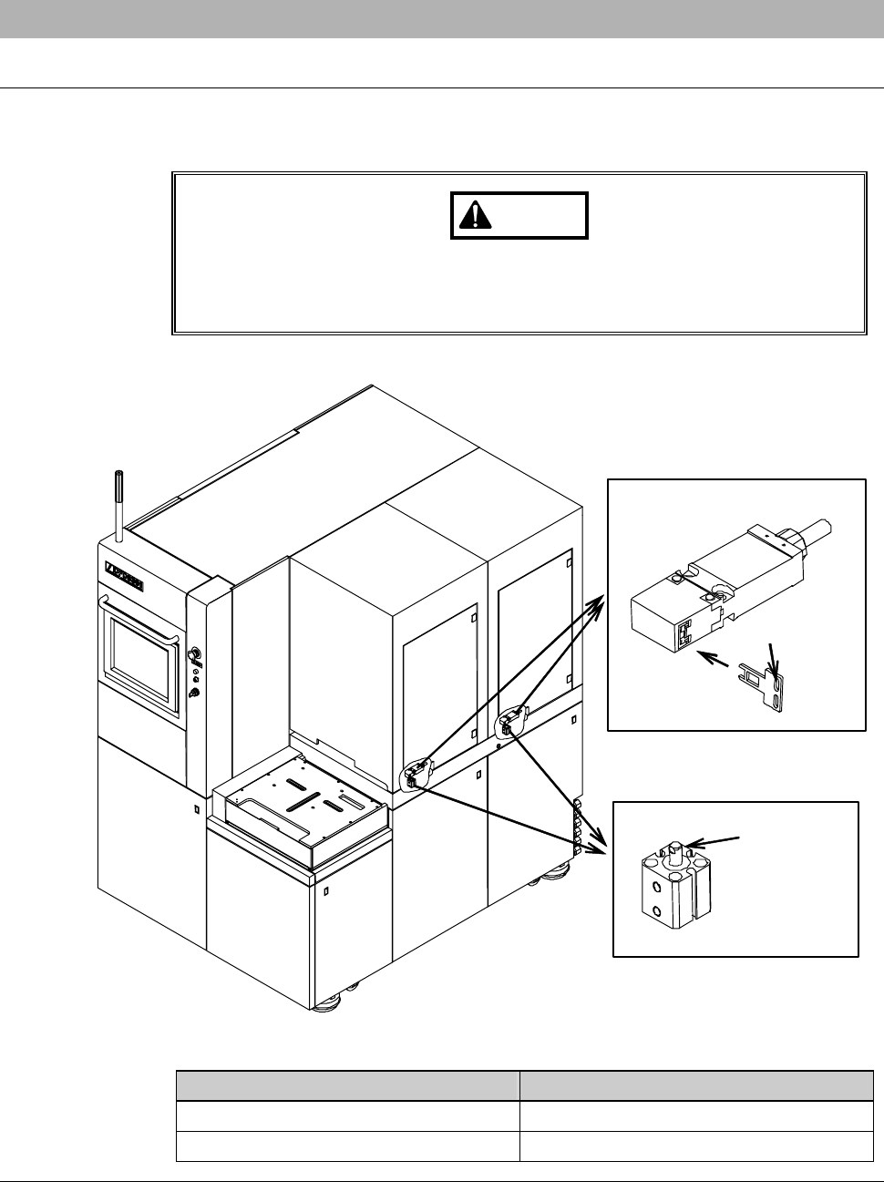
4-1-2. Safety switch/lock cylinder of the arm section cover
Location and structure of the safety switch and lock cylinder
The figure below shows the location and structure of the safety switch and
lock cylinder.
WARNING
Ensure to install the safety switch and lock cylinder under the
condition in which they function normally. Also, be sure to use the
safety switch and lock cylinder specified by DISCO.
ÿ
Lock cylinder
Cylinder rod
Lock key
Safety switch
Part Name Part No.
Safety switch BAZY1DSS4045
Lock cylinder MOJKLB45

A-49
4-2. Machine Protection
Summary of this section
For the purpose of machine protection, the machine incorporates the interlocks
for supply pressure of air and clean air pressure, flow rate of wheel and spindle
coolant water and vacuum pressure.
Section No. Title Contents
4-2-1 Air pressure sensor - Location of the air pressure
sensor
- Structure of the air pressure
sensor
4-2-2 Flow rate sensor - Location of the flow rate sensor
- Structure of the flow rate sensor
4-2-3 Vacuum pressure sensor - Monitoring section of vacuum
pressure sensor
- Vacuum pressure sensor reading
- Energy-efficient mechanism of
vacuum system
4-2-4 Sensor for clean air,
vacuum and deionized
water pressure
- Structure of the pressure sensors
for clean air, vacuum and
deionized water
A-50
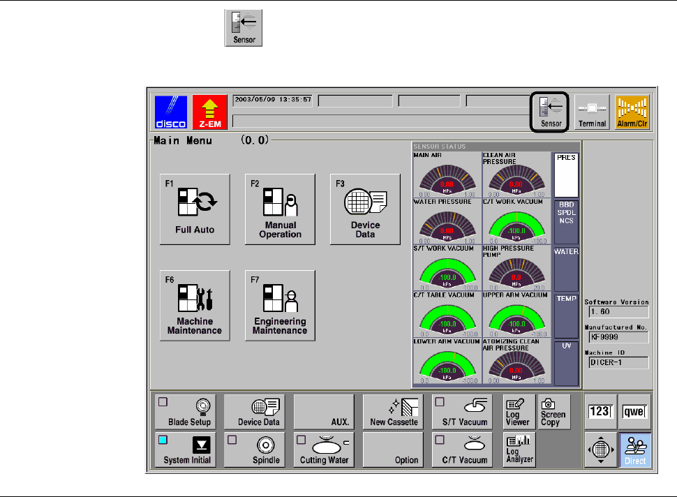
How to display readings of utilities
If you press button, you can obtain readings of utilities, whenever you
want.