DFD6361-Maintenance.pdf - 第68页
A-52 4-2-2. Flo w rate sensor Flow r ate sensor To protect the machine and workpiec es during cutting, the interlocks for th e wheel and spindl e coolant water a re provided with the m achine. The location and structure …
A-51
4-2-1. Air pressure sensor
Air pressure sensor
For machine protection, the machine incorporates the interlocks for air supply
pressure.
The location and structure of the air pressure sensor are as illustrated below.
For the method to adjust the sensor, see the section B-4, [Sensor Adjustment].
[U]
LEFT SIDE
Air pressure sensor
Checking Sensor Name Part No. Limit Setting
Pressure Value
Air pressure Pressure switch MOJKH018 0.4MPa
A-52
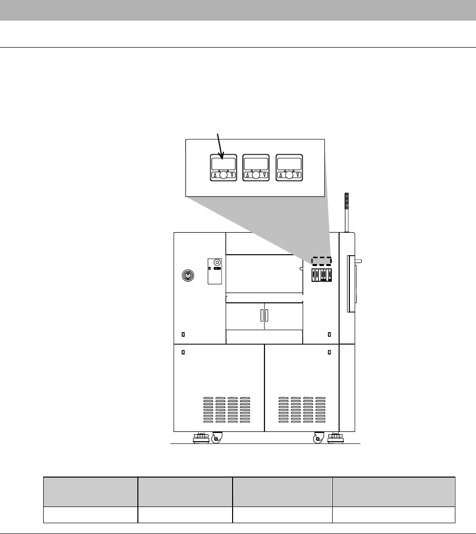
4-2-2. Flow rate sensor
Flow rate sensor
To protect the machine and workpieces during cutting, the interlocks for the
wheel and spindle coolant water are provided with the machine.
The location and structure of the spindle coolant water flow rate sensor are as
illustrated below.
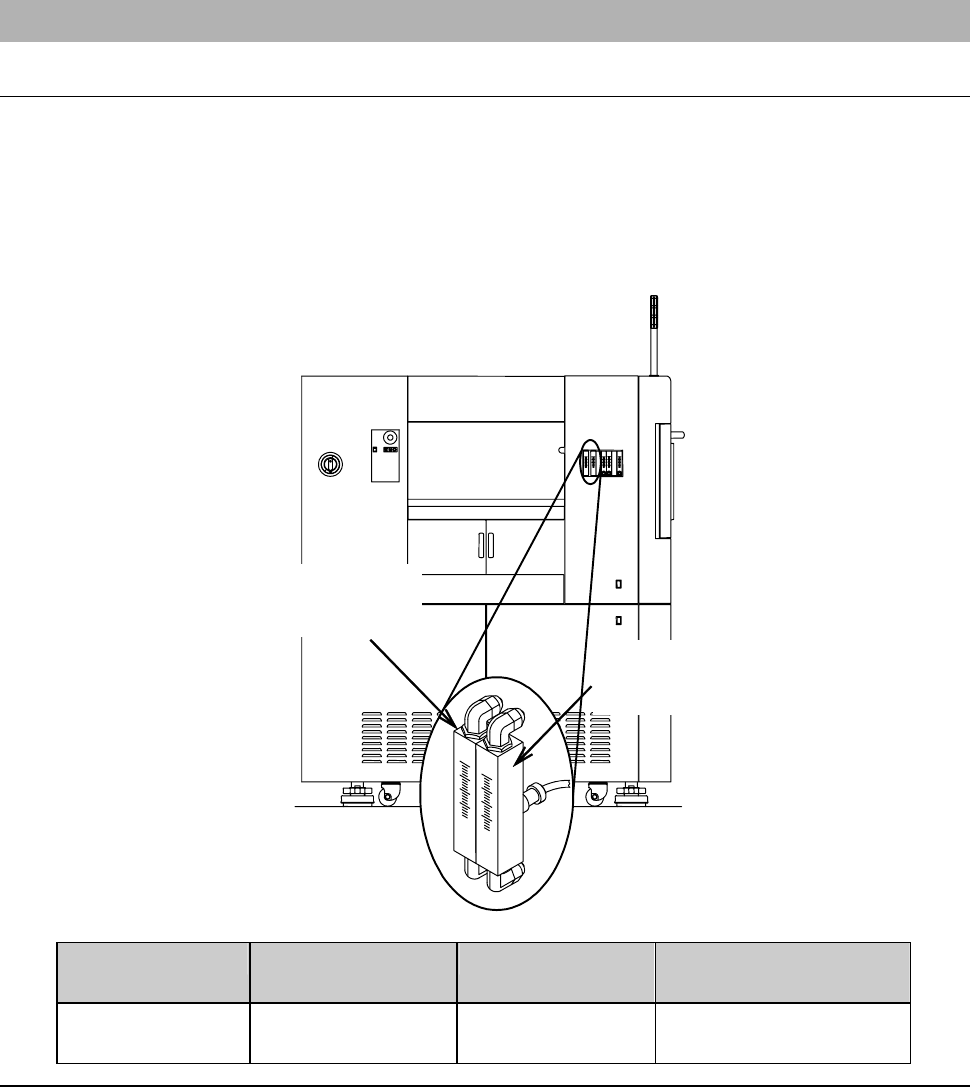
[Spindle coolant water flow rate sensor (Z1- and Z2-axis)]
Spindle1axis
spindle coolant water
flow rate sensor (Z1)
Spindle 2 axis
spindle coolant water
flow rate sensor (Z2)
Checking Sensor Name Part No. Limit Setting
Flow Rate
Spindle axis
coolant water
Flow checker MOHEH058--C 1.0 L/min
A-53
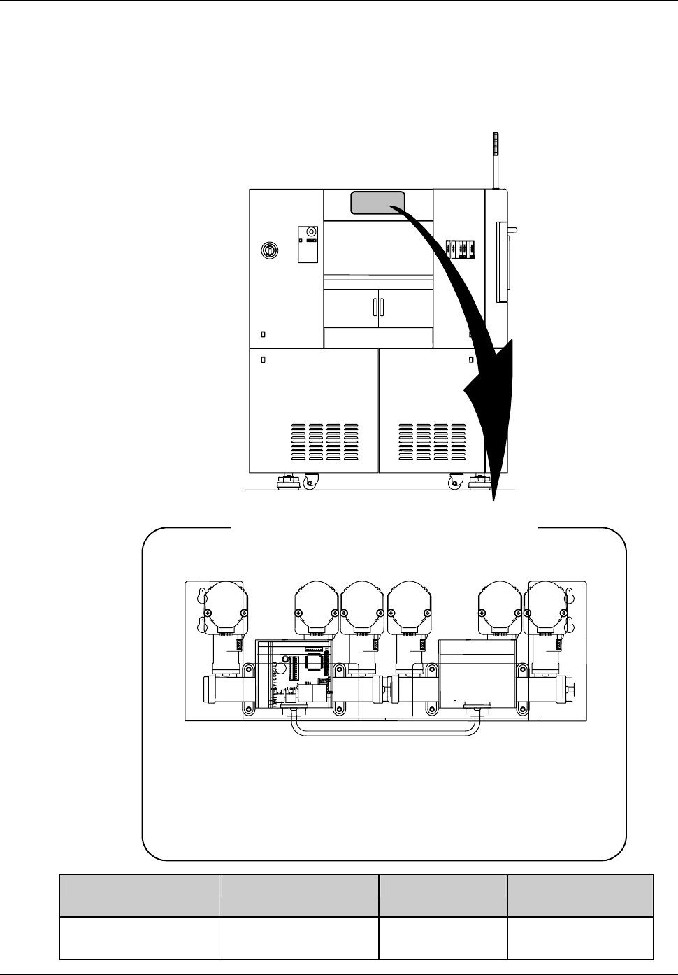
Wheel coolant water flow rate controller
The wheel coolant water flow rate controller monitors and controls the flow
rate of the wheel coolant water. The minimum limit of the flow rate is
programmed by software.
- The machine incorporating the mixed-fluid nozzle does not have controllers
of C and D.
ÿ
A B C D E F
[Wheel coolant water flow rate controller]
A : Z1 axis blade cooler
B : Z1 axis shower
C:Z1axisspray
D : Z2 axis blade cooler
E : Z2 axis shower
F:Z2axisspray
Checking Sensor Name Part No. Flow Rate Check
Setting Range
wheel coolant water Wheel coolant water
flow rate controller
MOKFH13351 0.2 to 2 L/min