DFD6361-Maintenance.pdf - 第696页
F-126 5-4-2. Disc onnecting pipi ng and wiring Procedur es for discon necting pipi ng and w iring Step No. Do This 1 Disconnect the tubes of t he controllers for the wheel coolant water flow rate. - The tubes are connect…
F-125
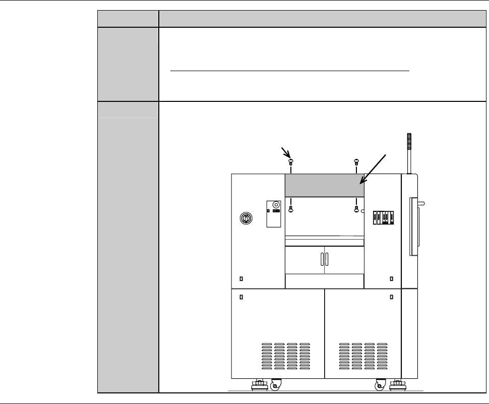
Procedures for removing the machine outer cover (Continued)
Step No. Do This
6
Remove the partition (left). Then store it sufficiently away from
the working area.
- For the removal procedures of the partition (left);
See the section 1-2-3-2 of this chapter, [Removing the partition
(left)].
7
Remove the cover. Then store it sufficiently away from the
working area.
ÿ
Cross-shaped recess screws
Cover
Continued in the next section.
F-126
5-4-2. Disconnecting piping and wiring
Procedures for disconnecting piping and wiring
Step No. Do This
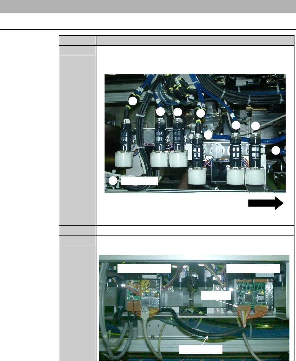
1
Disconnect the tubes of the controllers for the wheel coolant
water flow rate.
- The tubes are connected by one-touch joints.
TOP SIDE
Machine front
: Remove it.
2
Open the covers of the circuit board box 1 and 2.
3
Disconnect the connector of the coupling cable which is
connected with the circuit board 2.
Circuit board box 2Circuit board box 1
Connector
Coupling cable
F-127
Procedures for disconnecting piping and wiring (Continued)
Step No. Do This
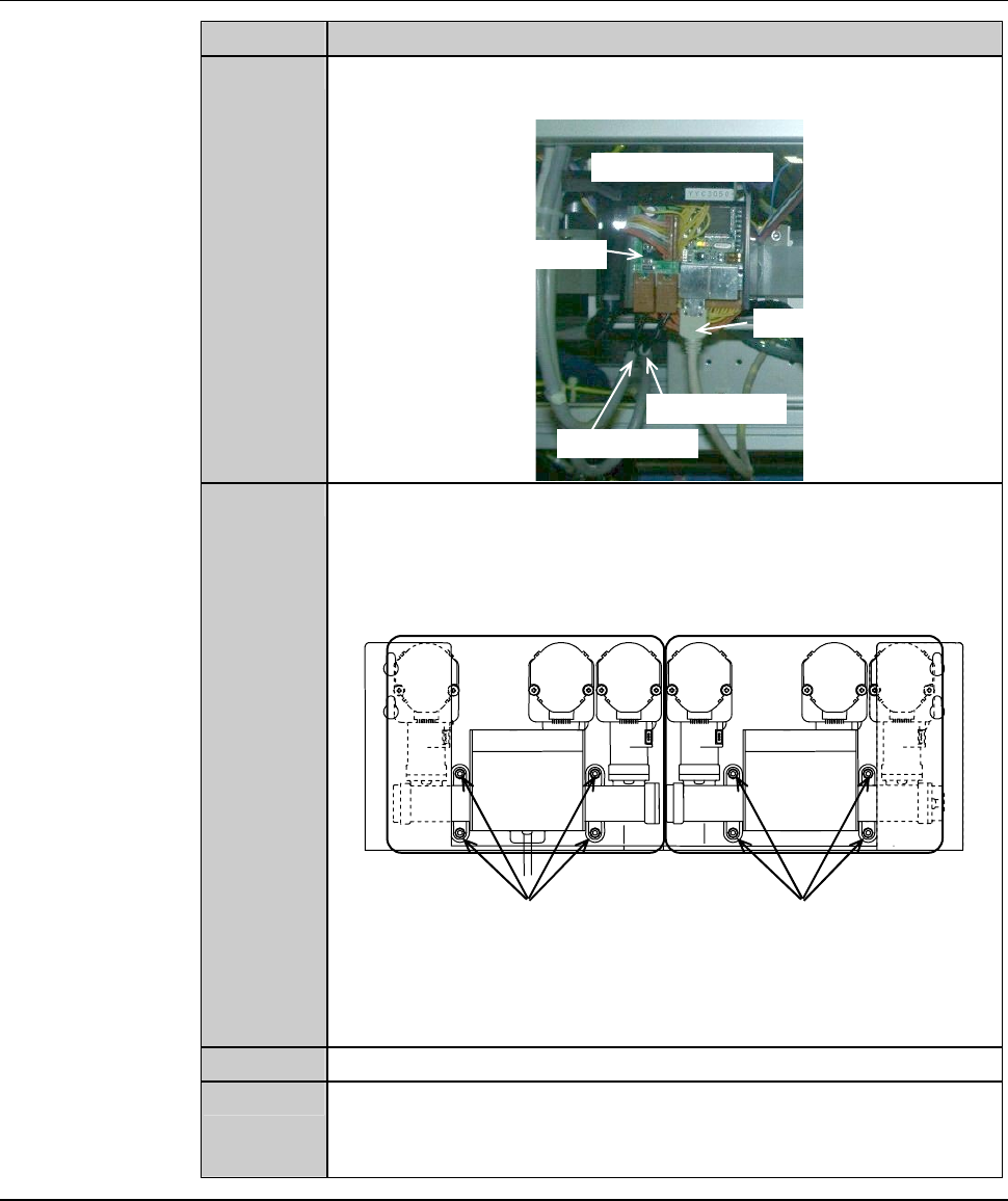
4
From the main board in the circuit board box 1, disconnect the
power cable A and B and AE-LINK cable.
Circuit board box 1
AE-LINK cable
Power cable B
Power cable A
Main board
5
Remove the retaining screws of the controller unit for the wheel
coolant water flow rate.
Retaining screw (M4) Retaining screw (M4)
[Controller unit for wheel coolant water flow rate]
A B C D E F
For Z1-axis
A : Z1 axis blade cooler
B:Z1axisshower
C:Z1axisspray
D : Z2 axis blade cooler
E : Z2 axis shower
F:Z2axisspray
For Z2-axis
6
Pull the controller unit out of the machine.
7
Disconnect the joints on the controller unit.
- There are six joints on the upper part of the controller unit and
two on the lower part.
Continued in the next section.