DFD6361-Maintenance.pdf - 第698页
F-128 5-4-3. Re placing t he controller for t he wheel cool ant water flow rate Procedur es for replaci ng the controller for the wheel cool ant water flow rate Step No. Do This 1 Replace the controll er unit for the whe…
F-127
Procedures for disconnecting piping and wiring (Continued)
Step No. Do This
4
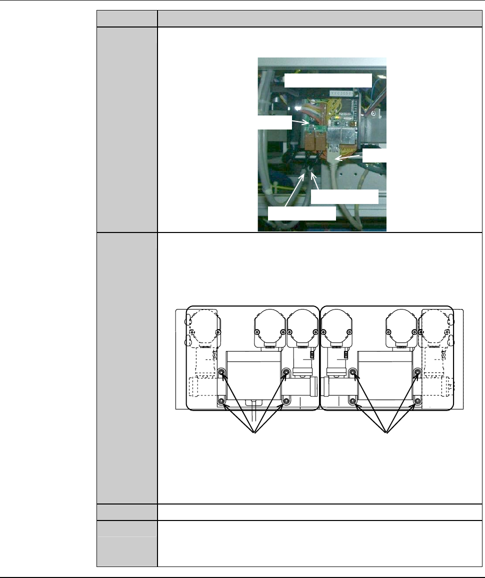
From the main board in the circuit board box 1, disconnect the
power cable A and B and AE-LINK cable.
Circuit board box 1
AE-LINK cable
Power cable B
Power cable A
Main board
5
Remove the retaining screws of the controller unit for the wheel
coolant water flow rate.
Retaining screw (M4) Retaining screw (M4)
[Controller unit for wheel coolant water flow rate]
A B C D E F
For Z1-axis
A : Z1 axis blade cooler
B:Z1axisshower
C:Z1axisspray
D : Z2 axis blade cooler
E : Z2 axis shower
F:Z2axisspray
For Z2-axis
6
Pull the controller unit out of the machine.
7
Disconnect the joints on the controller unit.
- There are six joints on the upper part of the controller unit and
two on the lower part.
Continued in the next section.
F-128
5-4-3. Replacing the controller for the wheel coolant water
flow rate
Procedures for replacing the controller for the wheel coolant water flow rate
Step No. Do This
1
Replace the controller unit for the wheel coolant water flow rate
to the new one.
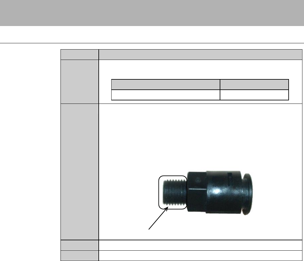
Name Part No.
Controller MOKFH133
2
Connect the joints to the controller unit.
- In order to prevent water leakage, use seal tape or so in
connection of piping.
- Take care so that any piece of the seal tape used for piping will
not get into the pipe.
Wind the seal tape here.
3
Reinstall the new controller unit in its original position.
4
Connect the tubes to the joints.
F-129
Procedures for replacing the controller for the wheel coolant water flow rate (Continued)
Step No. Do This
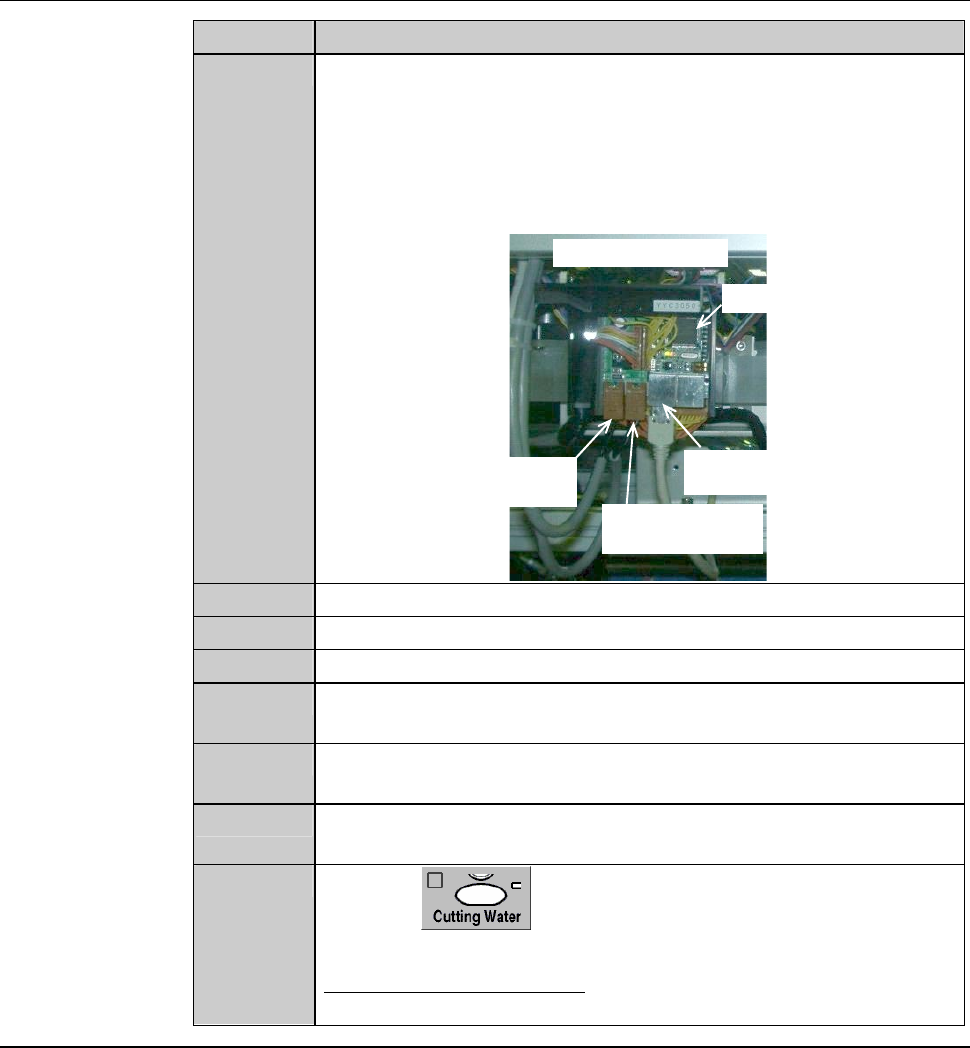
5
Connect the power cable A and B and AE-LINK cable to the
main board in the circuit board box 1.
- The connection port for the power cable A is located on your
left and that for cable B is on your right.
- The connection port for AE-LINK cable is the left side one of
the two lining abreast.
Circuit board box 1
Connection port for
AE-LINK cable
Main board
Connection port
for power cable A
Connection port
for power cable B
6
Connect the coupling cable to the circuit board box 2.
7
Reinstall the cover.
8
Reinstall the partition (left).
9
Turn ON the facility power source and open the main valve of
the wheel coolant water.
10
Open the circuit breaker lever lockout and then turn ON the
circuit breaker.
11
Insert the key into the main switch and then turn ON the main
switch.
12
Press the to turn ON the wheel coolant water. Then
make sure that there is no water leakage.
- If you find water leakage;
Repeat the procedures of this section beginning with the step 1.