DFD6361-Maintenance.pdf - 第7页
Contents-1 CONTENTS READ CARE FULL Y BEFO RE USING T HIS MANUAL INTRODU CTION ................................................ Intro-1 CONTEN TS ................................................. Contents-1 A. MACHINE COM…
Intro-2
Part replacement
For parts replacement, be sure to use genuine Disco brand parts. If any parts
that are not of genuine Disco brand are used for replacement, Disco shall
assume no liability for any damages caused by these parts.
For replacement of components that use parts accredited as UL Standards
products, be sure to replace them respectively to new components that use UL
Standards products.
For replacement of critical parts, be sure to contact your nearest Disco office
first for prior consultation. If any critical parts are replaced without consulting
Disco beforehand, Disco shall assume no liability for any consequences
arising therefrom.
Part warranty period
Part warranty period is as follows:
Part Warranty Period
Electrical parts having contact points Six months from the B/L date
Consumable parts Not covered
Parts other than the above 12 months from the B/L date
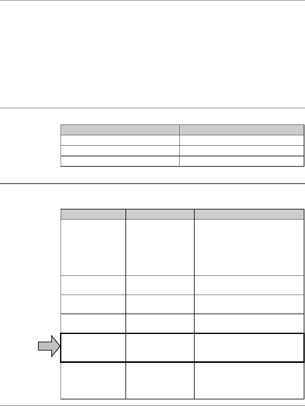
Documentation for this machine
The following six written manuals are provided for 6000 series machine.
This manual is the Maintenance Manual indicated by the arrow.
Manual Who should read Contents
Safety Manual - Management
representative
- Data maintenance
personnel
- Maintenance
personnel
Information for ensuring safety
during machine operation,
installation and maintenance
Installation Manual Maintenance
personnel
Procedures for machine
installation and adjustment
Operation Manual Operator Operational procedures to be
performed by operators
Data Maintenance
Manual
Data maintenance
personnel
Screen contents for data entry and
data setting procedures
Maintenance
Manual
Maintenance
personnel
Servicing, inspection and
adjustment procedures to be
performed by customers
Technical
Reference
Maintenance
personnel
Machine specifications/circuit
diagrams
Illustrations
Part lists

Contents-1
CONTENTS
READ CAREFULLY BEFORE USING THIS MANUAL
INTRODUCTION................................................Intro-1
CONTENTS.................................................Contents-1
A. MACHINE COMPONENTS AND
FUNCTIONS.......................................................A-1
1. Machine Outer Cover............................................................................. A-2ÿ
2. Axis Section............................................................................................ A-7ÿ
2-1. AxisArrangement.............................................................................................A-9ÿ
2-2. X-axis Section ................................................................................................ A-11ÿ
2-3. Y (Y1 and Y2)-axis Section.............................................................................A-13ÿ
2-4. Z (Z1 and Z2)-axis Section.............................................................................A-16ÿ
2-5. θ-axis Section.................................................................................................A-18ÿ
2-6. Spinner Section..............................................................................................A-21ÿ
2-7. Elevator Section.............................................................................................A-23ÿ
2-8. Pre-alignment Section....................................................................................A-28ÿ
2-9. Transport Section...........................................................................................A-30ÿ
2-10. Microscope Section......................................................................................A-32ÿ
2-11. Spindle-axis Section .....................................................................................A-35ÿ
3. Main Body Section ............................................................................... A-38ÿ
4. Detection Function ............................................................................... A-45ÿ
4-1. Personnel Protection......................................................................................A-46ÿ
4-1-1. Safety switch/lock cylinder of the splash cover.....................................A-47ÿ
4-1-2. Safety switch/lock cylinder of the arm section cover.............................A-48ÿ
4-2. Machine Protection.........................................................................................A-49ÿ
4-2-1. Air pressure sensor...............................................................................A-51ÿ
4-2-2. Flow rate sensor ...................................................................................A-52ÿ

Contents-2
CONTENTS
4-2-3. Vacuum pressure sensor ......................................................................A-54ÿ
4-2-4. Sensor for clean air and deionized water..............................................A-56ÿ
B. ADJUSTMENT OPERATION..............................B-1
1. Chuck Table Replacement...................................................................... B-2ÿ
1-1. Removing the chuck table................................................................................B-4ÿ
1-2. Mounting the chuck table..................................................................................B-7ÿ
2. Flange/Hub Mount Replacement............................................................ B-9ÿ
2-1. Flange Replacement (1.2 kW Spindle)........................................................... B-11ÿ
2-1-1. Removing the flange (1.2 kW spindle)..................................................B-14ÿ
2-1-2. Mounting the flange (1.2 kW spindle)....................................................B-18ÿ
2-2. Hub Mount Replacement (1.2 kW Spindle).....................................................B-24ÿ
2-2-1. Removing the hub mount (1.2 kW spindle)...........................................B-27ÿ
2-2-2. Mounting the hub mount (1.2 kW spindle) ............................................B-31ÿ
2-3. Flange Replacement (1.8 kW Spindle)...........................................................B-38ÿ
2-3-1. Removing the flange (1.8 kW spindle)..................................................B-41ÿ
2-3-2. Mounting the flange (1.8 kW spindle)....................................................B-45ÿ
2-4. Hub Mount Replacement (1.8 kW Spindle).....................................................B-51ÿ
2-4-1. Removing the hub mount (1.8 kW spindle)...........................................B-54ÿ
2-4-2. Mounting the hub mount (1.8 kW spindle) ............................................B-58ÿ
2-5. Flange Replacement (2.2 kW Spindle)...........................................................B-64ÿ
2-5-1. Removing the flange (2.2 kW spindle)..................................................B-67ÿ
2-5-2. Mounting the flange (2.2 kW spindle)....................................................B-71ÿ
2-6. Hub Mount Replacement (2.2 kW Spindle).....................................................B-77ÿ
2-6-1. Removing the hub mount (2.2 kW spindle)...........................................B-80ÿ
2-6-2. Mounting the hub mount (2.2 kW spindle) ............................................B-84ÿ
3. Changing the Frame Size..................................................................... B-90ÿ
3-1. Calling up the CHANGE FRAME SIZE Screen [Screen 6.1]..........................B-91ÿ
3-2. Changing the Lower Arm Size........................................................................B-93ÿ
3-3. Changing the Upper Arm Size........................................................................B-95ÿ
3-4. Replacing the Spinner Table...........................................................................B-96ÿ
3-4-1. Removing the spinner table ..................................................................B-97ÿ
3-4-2. Mounting the spinner table....................................................................B-99ÿ
3-5. Changing the Frame Clamp Size .................................................................B-100ÿ
3-6. Completion of Frame Size Change ..............................................................B-102ÿ