DFD6361-Maintenance.pdf - 第78页
B-6 Procedur es for re moving the c huck table (Conti nued) Step No. Do This 6 Press the <F1> button t o call up CHANGE FRAME S IZ E s creen [screen 6.1] . ÿ G 0 1 0 2 P r e s sE N T E Rt ow r i t ed a t a . 8 2-8-…
B-5
Procedures for removing the chuck table (Continued)
Step No. Do This
4
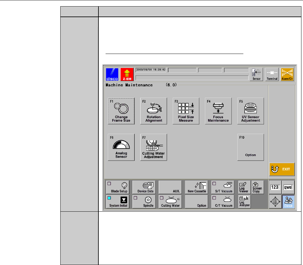
Press the <F6> button to call up MACHINE MAINTENANCE
screen [screen 6.0].
- User password input is required to call up this screen.
- For the MACHINE MAINTENANCE screen,
see the section B-6-1 of the Data Maintenance Manual.
5
Make sure that both the spindle rotation and the wheel coolant
water come to a complete stop.
- If the spindle still rotates,
press the <Spindle> button to stop its rotation.
- If the wheel coolant water is still supplied,
press the <Cut Water> button to stop is supply.
B-6
Procedures for removing the chuck table (Continued)
Step No. Do This
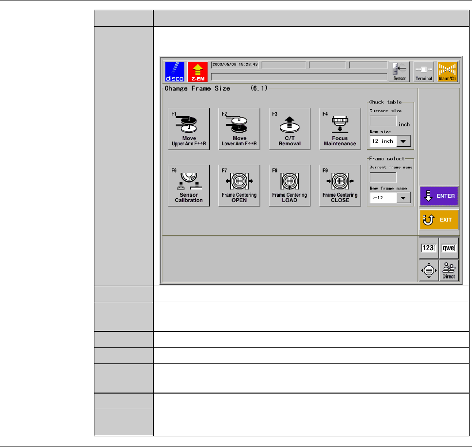
6
Press the <F1> button to call up CHANGE FRAME SIZE screen
[screen 6.1].
ÿ
G0102 PressENTERtowritedata.
8
2-8-1
7
Press the <F3> button to turn OFF the chuck table vacuum.
8
Press the Disco's logo button at the upper left corner of the screen
in order to lock up the touch panel.
9
Open the front arm section cover.
10
Remove the chuck table.
11
With a lint-free cloth moistened with alcohol, clean the removed
chuck table.
12
Enclose the cleaned chuck table in the packing material which
was supplied at the time of machine delivery, and then store the
chuck table.
Continued in the next section.
B-7
1-2. Mounting the chuck table
Procedures for mounting the chuck table
Step No. Do This
(Continued from the previous section)
1
With a lint-free cloth moistened with alcohol, clean the chuck
table to be installed and the table base.
2
Check the position of the notch on the side of the chuck table.
3
Set the chuck table on the table base so that the notch points the
front of the machine.
- When the chuck table is properly placed, the protrusion of the
chuck table backside mates with the hole of the table base.
4
Press the <Close> button to release lock of the touch panel.
5
Turn ON the vacuum system by pressing the <F3> button to
secure the chuck table.
6
Close the front arm section cover.
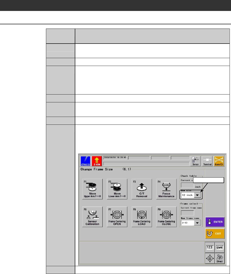
7
Enter the size of the installed chuck table in C/T (chuck table
size) column of CHANGE FRAME SIZE screen [screen 6.1].
- In the example screen shown below, 12-inch chuck table is
used.
ÿ
Select data here
G0102 PressENTERtowritedata.
8
2-8-1
8
Press the <ENTER> button to finalize the data.