DFD6361-Maintenance.pdf - 第88页
B-16 Procedur es for re moving the fl ange (1. 2 kW s pindle) St e p N o . Do This 1 Call up the B LADE REPLACEMENT screen [ screen 4.1] . - The Y -axis moves to its origin position. 2 Make sure that the spindle is OFF .…
B-15
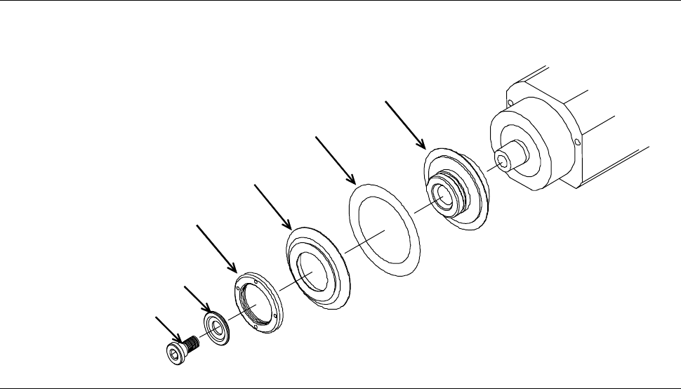
Exploded view of flange and blade (1.2 kW spindle)
The flange and blade are to be mounted as illustrated below.
[1.2 kW spindle: R-type flange]
Flange B
Flange A
Flange B lock nut
Blade
Lock bolt
Washer
B-16
Procedures for removing the flange (1.2 kW spindle)
Step No. Do This
1
Call up the BLADE REPLACEMENT screen [screen 4.1].
- The Y-axis moves to its origin position.
2
Make sure that the spindle is OFF.
3
Press the Disco's logo button located at the upper left of the
screen to lock up the touch panel.
4
Open the splash cover.
5
Remove the flange B lock nut, flange B and blade.
- For procedures to remove them;
See the section B-6 of Operation Manual, [Blade Maintenance].
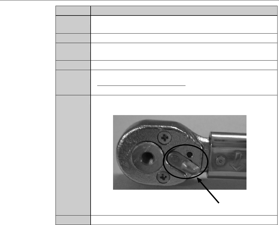
6
Adjust the direction selector lever so that the wrench does not
turn free when you turn the torque wrench counterclockwise.
Direction selector lever
7
Have on hand the torque wrench set.
B-17
Procedures for removing the flange (1.2 kW spindle) (Continued)
Step No. Do This
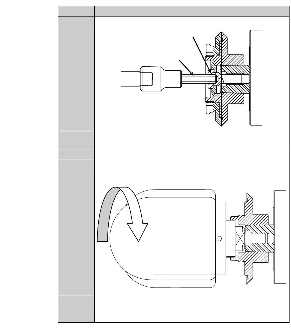
8
Insert the bit into the center hole of the lock bolt.
Lock bolt
Bit
9
Turn the torque wrench counterclockwise.
- The lock bolt rotates counterclockwise and comes loose.
10
Remove the lock bolt and washer.
11
Screw the removing jig in the flange A until the jig reaches the
head of the spindle.
- In order to screw in the removing jig, turn it clockwise.
Turn the jig
clockwise.
12
When the removing jig contacts with the tip of the spindle, give
the jig another clockwise turn.
- The flange A comes off the spindle.
Continued in the next section.