DFD6361-Maintenance.pdf - 第94页
B-22 Procedur es for mo unting the fl ange (1. 2 kW spi ndle) St e p N o . Do This (Continued from the previous section) 1 Clean the flange A and spindle taper se ction with lint-free waste moistened with alcohol, and th…
B-21
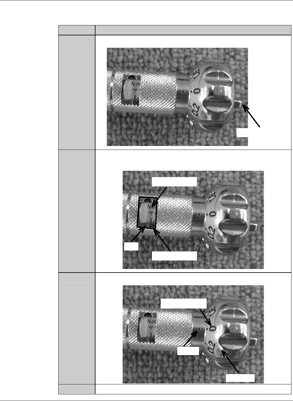
Procedures to adjust the torque of the torque wrench
As an example, the table below shows the procedure to adjust the torque of the
torque wrench to 4.0N
⋅m.
Step No. Do This
1
Loosen the wing bolt at the tail of the torque driver.
Wing bolt
2
Turn the handle to align the calibration of 4 with the mark of the
torque indicator.
Torque indicator
Mark
Calibration
3
Align the dial scale of 0 to the mark of the handle.
Handle
Mark
Dial scale
4
Tighten the wing bolt at the tail of the torque driver.
B-22
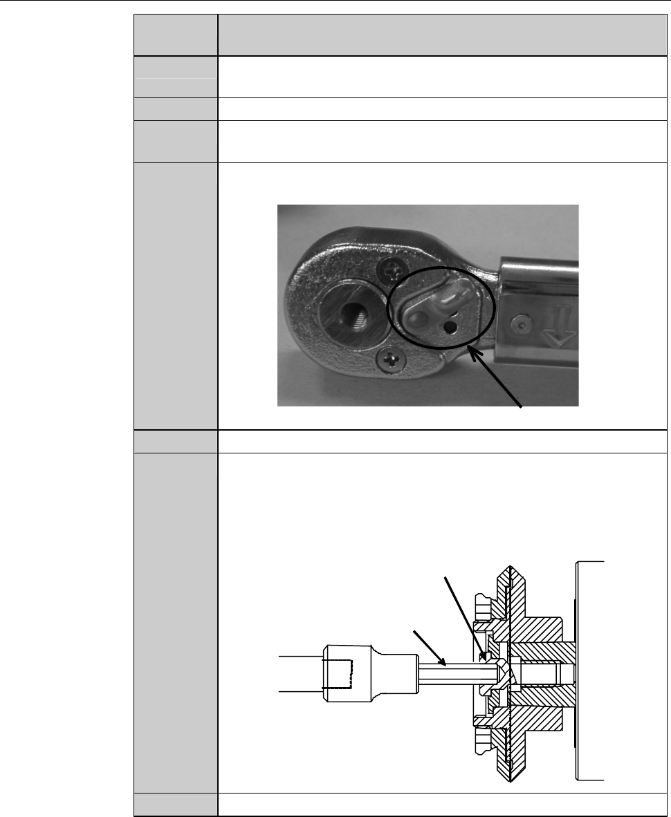
Procedures for mounting the flange (1.2 kW spindle)
Step No. Do This
(Continued from the previous section)
1
Clean the flange A and spindle taper section with lint-free waste
moistened with alcohol, and then blow air to remove water.
2
Fit the flange A onto the spindle taper section.
3
Adjust the torque of the torque wrench.
Torque for 1.2 kW spindle: 4.0 N·m
4
Adjust the direction selector lever so that specified torque will be
produced when you turn the torque wrench clockwise.
Direction selector lever
5
Have on hand the torque wrench set.
6
Using the torque wrench set, torque the lock bolt to 4.0 N·m.
- To tighten the bolt, turn the torque wrench clockwise.
- Turn the torque wrench slowly.
- When the torque reaches the specified one, you feel light
resistance.
Lock bolt
Bit
7
Close the splash cover.

B-23
Procedures for mounting the flange (1.2 kW spindle) (Continued)
Step No. Do This
(Continued from the previous section)
8
Press the <Close> button to release lock of the touch panel.
9
Press the <EXIT> button to call up the MAIN MENU
[screen 0.0].
10
Turn ON the spindle.
- Maximum rotating speed for 2-inch blade:
60,000 min
-1
(60,000 rpm)
11
Turn OFF the spindle.
12
Call up the BLADE REPLACEMENT screen [screen 4.1].
- The Y-axis moves to its origin position.
13
Press the Disco's logo button located at the upper left of the
screen to lock up the touch panel.
14
Open the splash cover.
15
Torque the lock bolt to 4.0 N·m again.
16
Press the <Close> button to release lock of the touch panel.
17
Perform a conditioning operation.
- For the conditioning procedures;
See the section C-2, [Hub Mount/Flange Conditioning].
18
Install the blade.
- For the blade installation procedure;
See the section B-6, [Blade Maintenance] of the Operation
Manual.
19
Close the splash cover.
20
Press the <System Initial> button to effect system initialization.