00194385-01.pdf - 第31页
Installation of retaining clamp for lif ting axis/alignment of spindle/check of gear fixing for spindle, MTC2 06/2004 Edition 31 2.4.2 Inserting the retaining clam p if the hole is at the front : Disconn ect both p lugs …
Installation of retaining clamp for lifting axis/alignment of spindle/check of gear fixing for spindle, MTC2
06/2004 Edition
30
: Turn the retaining clamp over to the left and insert the screw once more.
Only lightly tighten the screw so that the clamp can still be moved.
2
2
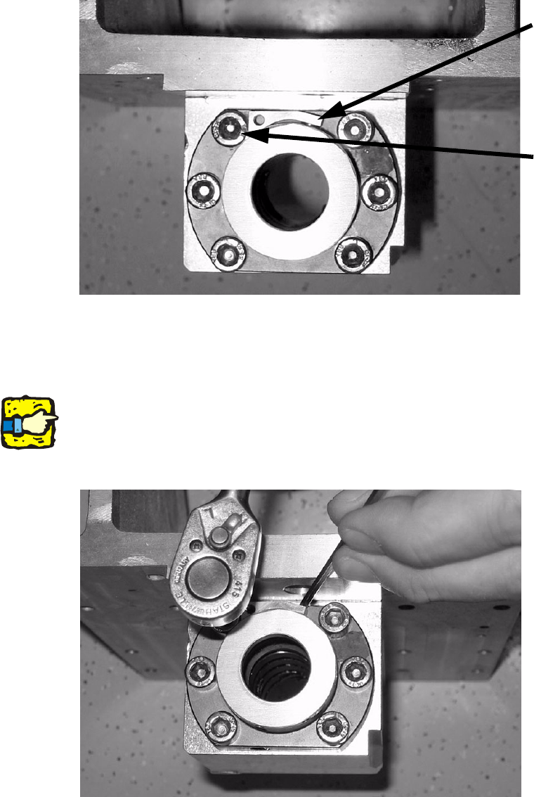
: Press the retaining clamp against the flanged nut using a suitable tool as shown in the picture
so that the clamp lies fully against it, then tighten the screw.
2
2
2
2
The clamp must lie fully against the nut to prevent the aluminum cover of the spindle nut flapping
up. 2
2
2
2
Retaining clamp
Screw
Installation of retaining clamp for lifting axis/alignment of spindle/check of gear fixing for spindle, MTC2
06/2004 Edition
31
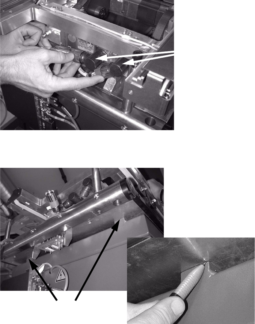
2.4.2 Inserting the retaining clamp if the hole is at the front
: Disconnect both plugs from the motor.
2
2
: Mark the positions of the docking plate on the bases (using a felt-tip pen, etc).
2
2
Remove both plugs
Mark the positions here
Installation of retaining clamp for lifting axis/alignment of spindle/check of gear fixing for spindle, MTC2
06/2004 Edition
32
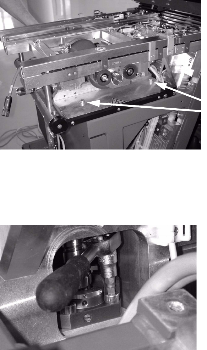
: Loosen the six screws in order to pull the plate forward.
2
2
: Pull the docking plate forward in order to access the flanged nut.
It may be necessary to undo some cable ties in order to do this.
2
: Loosen the screw using the ratchet screwdriver with the size 4 hexagon head.
2
2
2
Loosen six screws
on the docking plate