00194385-01.pdf - 第37页
Installation of retaining clamp for lif ting axis/alignment of spindle/check of gear fixing for spindle, MTC2 06/2004 Edition 37 2.6.1 Assembly : Reset the b asic hei ght of the MT C2 to th e original value (see ope rati…
Installation of retaining clamp for lifting axis/alignment of spindle/check of gear fixing for spindle, MTC2
06/2004 Edition
36
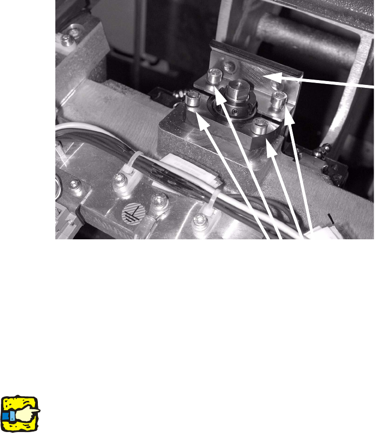
: Loosen the four screws on the top spindle block (see photograph).
: Remove the two screws used to fix the plate, then remove the plate.
Turn the screws loosely in the thread without tightening them.
2
: Move the tray supply into the top position.
The spindle can now be aligned.
If the spindle block is moved as the tray supply rises, the spindle was twisted when it was fitted.
It is now aligned correctly.
: Refit the plate and tighten the screws using a diagonal sequence.
: Move the tray supply into the refill position and insert a cassette.
2
2
2
2
Make sure there is a gap between cassette and plate. 2
2
2
2
2
2
2
Screws
Plate
Installation of retaining clamp for lifting axis/alignment of spindle/check of gear fixing for spindle, MTC2
06/2004 Edition
37
2.6.1 Assembly
: Reset the basic height of the MTC2 to the original value (see operating instructions for MTC2).
: Screw the cover shown in the picture back on again on the right and left.
Do not refit the other covers.
2
2
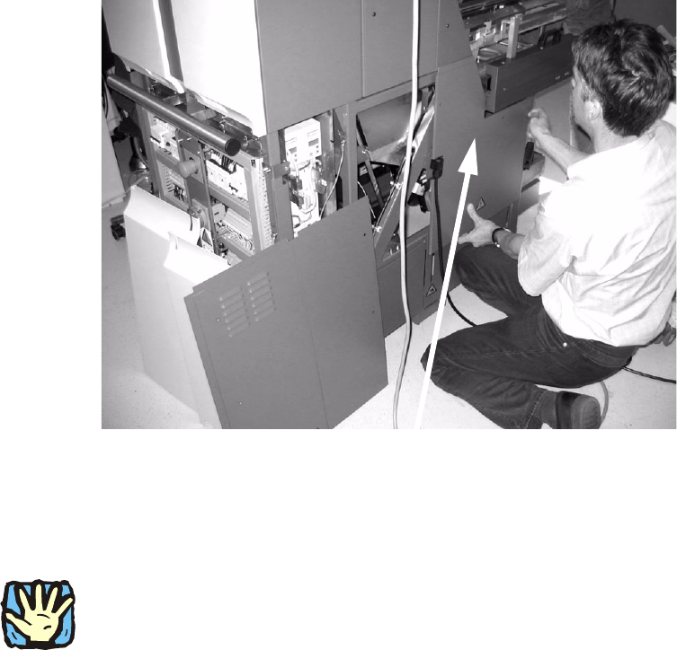
: Dock the MTC2 into the placement machine again.
2
Make sure that there are no people around the placement machine since there are live, unpro-
tected parts in the machine during the following steps. 2
Never reach into the openings while the MTC2 is plugged in since the axes can move. 2
2
: Plug in the power plug of the MTC2.
: Carry out a reference run.
: Insert the two bottom cassettes into the tray supplies once more.
2
2
2
2
Cover
Installation of retaining clamp for lifting axis/alignment of spindle/check of gear fixing for spindle, MTC2
06/2004 Edition
38
: Now press the P key on the MasterDrive for the lifting axes for the right and left sides.
r000 appears on the MasterDrive display.
: Press the Up arrow key until the display reads r004.
: Press the P key again.
2
: Carry out several MTC2 reference runs.
As the tray supply moves up, read the current value on the MasterDrive display.
: Enter the two values for tray supply 1 and tray supply 2 on the form provided. When the work
is finished, fill this form out in full and fax it to the fax number shown on the form (+49 89 20800
35130).
2
: Switch the MTC2 off at the main switch.
: Remove the power plug from the MTC2.
: Dock the MTC2 out of the placement machine.
2
: Fit the remaining four covers and the two metal rails.
: Dock the MTC2 in again.
: Plug in the power plug of the MTC2 once more.
: Switch the MTC2 on at the main switch.
2
2
2
2
2
2
2
2
2
2
2
2