00900330-01_UM_ASM-ProcessLens_EN.pdf - 第35页
2 Safety 2.5 Safety features Instruction manual ASM ProcessLens 03/2021 35 Function The front protective hood cannot be opened (it is locked) unless the user actively presses the soft- ware button "Open front door&q…
2 Safety
2.5 Safety features
34 Instruction manual ASM ProcessLens 03/2021
2.5 Safety features
2.5.1 Protective hood, doors and covers
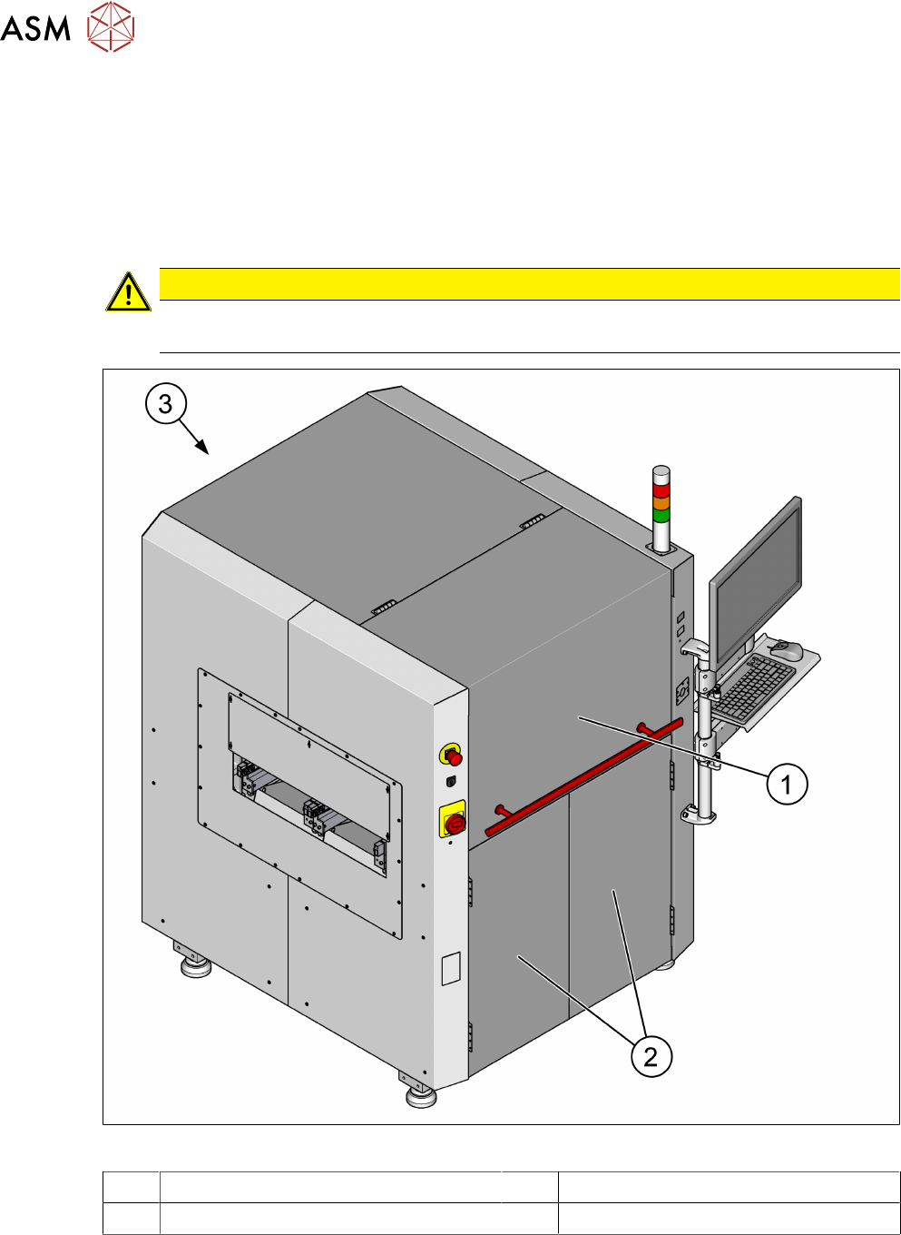
The travel range is covered with one movable protective hood (1) on the front side. The front pro-
tective hood (1), the front doors (2) and the rear cover (3) serve as protective devices which pre-
vent unauthorized access to the inside of the machine. The accessible front hood (1) and the front
doors (2) are interlocked. The rear cover is secured by allen key screws.
CAUTION
Risk of injury
Do not stand on or otherwise access the protective hoods and covers.
Fig.29: Protective hood, doors and covers
1 Front protective hood 2 Front doors
3 Rear cover

2 Safety
2.5 Safety features
Instruction manual ASM ProcessLens 03/2021 35
Function
The front protective hood cannot be opened (it is locked) unless the user actively presses the soft-
ware button "Open front door" from the ASM SPI GUI inspection software.
► Close the front protective hood and press the software button "Open front door".
► Press the START button (see item 1 in fig. "Position of buttons and switches" [}36]).
The software sequence for the START button as follows:
●
The software program will check if the front protective hood is closed from the safety door lock
close status and the EMERGENCY STOP button status.
●
If the front protective hood is closed and the EMERGENCY STOP button is not activated, the
software will lock the safety door lock and reset the safety controller.
●
The software will check the safety relay interlock is cleared before enabling the motors.
If the front door opens, the power supply to the axes will be immediately interrupted. The axes stop
moving.
See also
2 2.5.2.1 "Position of switches and buttons on the machine" [}36]
2 Safety
2.5 Safety features
36 Instruction manual ASM ProcessLens 03/2021
2.5.2 Switches and buttons on the machine
2.5.2.1 Position of switches and buttons on the machine
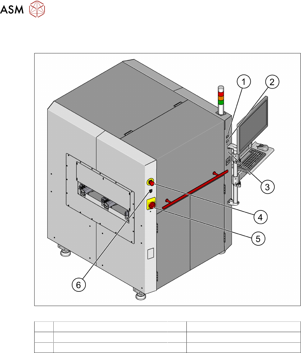
Fig.30: Position of buttons and switches
1 Start button (green) 2 Stop button (black)
3 External grounding point 4 EMERGENCY STOP button
5 Main switch 6 Key switch
2.5.2.2 Description of functions
Main power switch in ON position
After switching on the main power switch, 24 V DC and 240 V AC are present.
Main power switch in OFF position
(see 2.5.2.1 "Position of switches and buttons on the machine" [}36])
The main power switch disconnects the single phase from the power supply.