00900330-01_UM_ASM-ProcessLens_EN.pdf - 第48页
3 Machine description 3.1 Overview of the modules 48 Instruction manual ASM ProcessLens 03/2021 3.1.2 Inspection head Fig.34: Inspection head 1 Imaging module (camera and lens mount) 2 Right source of 3D light 3 Top LED…
3 Machine description
3.1 Overview of the modules
Instruction manual ASM ProcessLens 03/2021 47
3 Machine description
3.1 Overview of the modules
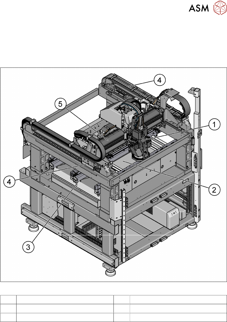
3.1.1 Overview of assemblies
Fig.33: Overview of assemblies
1 Inspection head 2 Lifting table
3 PCB conveyor assembly 4 Y-Movement for inspection head
5 X-Movement for inspection head
3 Machine description
3.1 Overview of the modules
48 Instruction manual ASM ProcessLens 03/2021
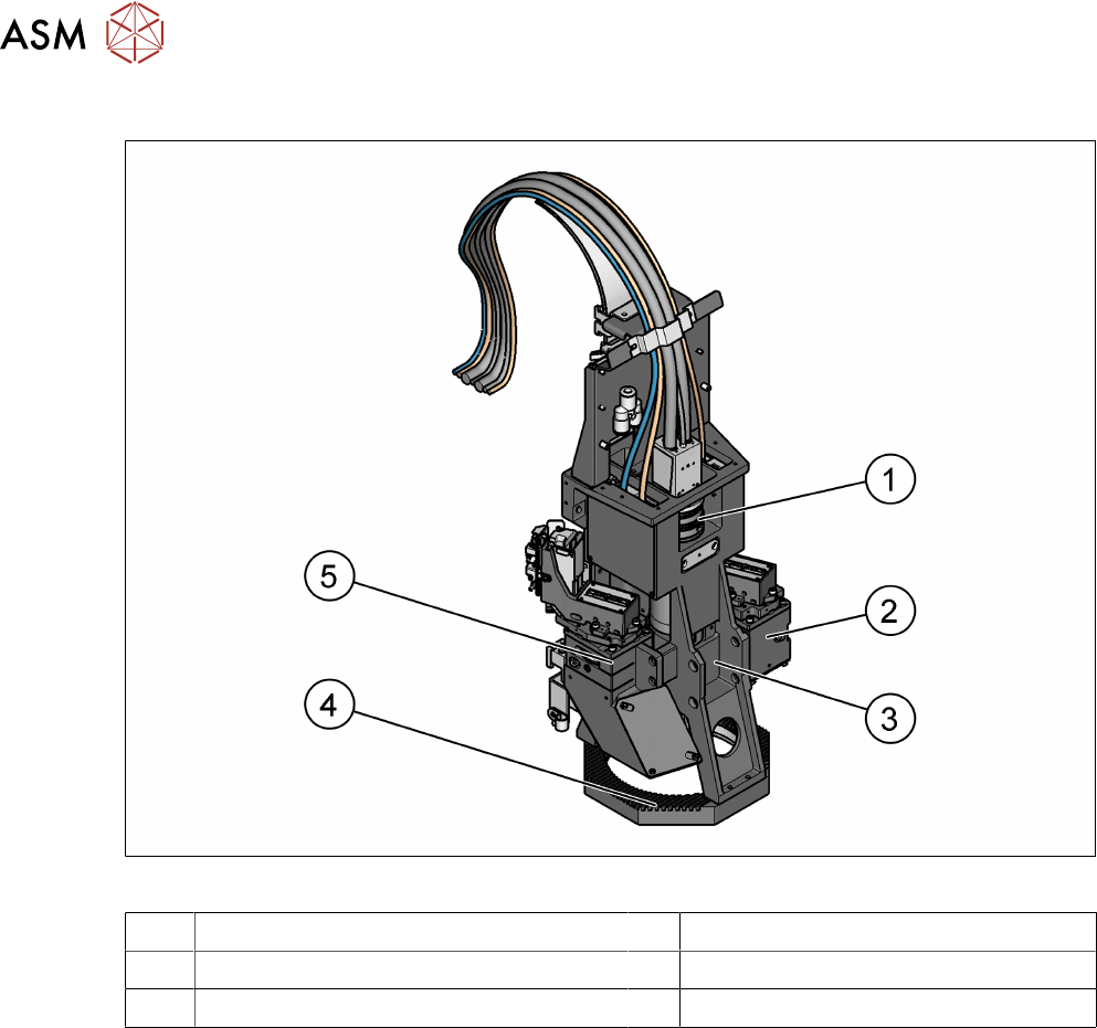
3.1.2 Inspection head
Fig.34: Inspection head
1 Imaging module (camera and lens mount) 2 Right source of 3D light
3 Top LED ring 4 Low LED ring
5 Left source of 3D light
3.1.2.1 Description
The optics head module, sitting on the gantry module, performs the image taking function, and
based on which, the expected inspection results are given.
The optics head module is split up into 2 parts, the DLP Projector Module and the Imaging Module.
The DLP projects fringes with different widths and frequencies onto the board, and the imaging
module grabs pictures and the system re-construct the 3D object based on those images taken.
3 Machine description
3.1 Overview of the modules
Instruction manual ASM ProcessLens 03/2021 49
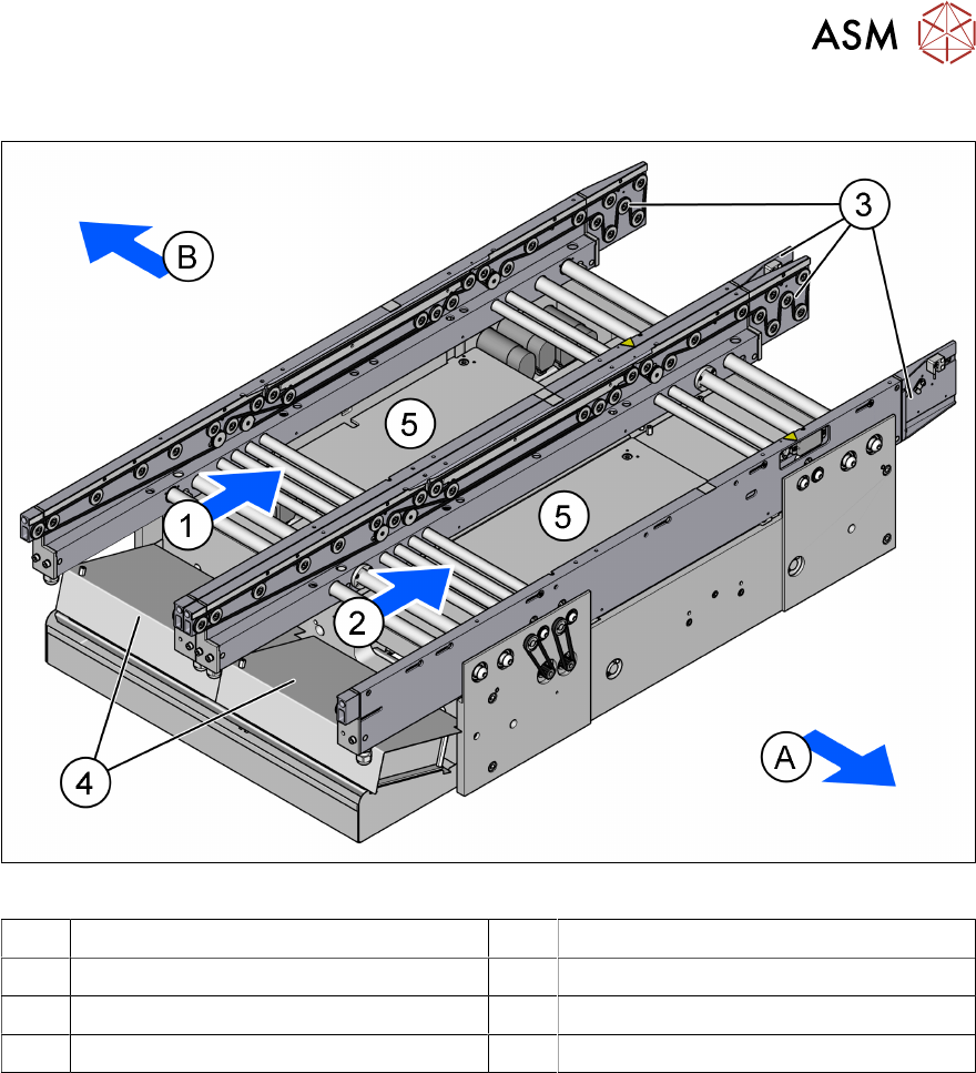
3.1.3 Dual conveyor assembly
Fig.35: PCB dual conveyor
A Front side of the machine B Rear side of the machine
1 Lane 1 2 Lane 2
3 Conveyor rails 4 Conveyor control units
5 Lifting tables
3.1.3.1 Description
The PCB conveyors are designed as three-part conveyors with input, processing and output con-
veyor sections. The two areas, input conveyor and output conveyor, serve as buffer zones for the
printed circuit boards.
The conveyor belts are driven by brushless DC motors. Light barriers monitor and control transport-
ation of the boards. Once the board has reached the placement area and has passed the light bar-
riers, it is braked. A laser light barrier records the position of the board. As soon as the circuit board
has reached its target position, the conveyor belt is stopped and the board is clamped from below.
The width of the circuit board conveyor is set and monitored by an integral control circuit. It can be
selected by calling up the program. The control electronics activate the drive motor until the re-
quired width has been reached. The width adjustment is therefore independent of other machine
components.
The conveyor height can be selected on the machine to allow the machines to be integrated into
lines with a conveyor height of, 900, 930 or 950 mm. The standard height is 930 mm.
The communication between the PCB conveyors of the individual machines takes places via the
SMEMA or IPC-HERMES-9852 interface.