SIPLACE D4-D4i 工程师手册_EN.pdf - 第63页
Service Work 4.2.5 Replacing the Tensioning Keys [00329478-01, 00 329485-01] G antr y Service Manual SIPLACE D4/D4i 63 Replacing the tensioning keys Legend 1 Tensioning key [00329478-01] 7 Spacer bolt with Benzing U-clip…

Service Work
Gantry 4.2.3 Replacing the X Axis Scale [00329316-01]
62 Service Manual SIPLACE D4/D4i
4.2.2.4
4.2.2.4 Installing the elastomeric spring
Installing the elastomeric spring
► Use the M8 x 20 hexagon socket-head screw to fix the elastomeric spring.
4.2.2.5
4.2.2.5 Settings
Settings
None
4.2.3
4.2.3 Replacing the X Axis Scale [00329316-01]
Replacing the X Axis Scale [00329316-01]
4.2.4
4.2.4 Replacing the Y-Axis Scale
Replacing the Y-Axis Scale
4.2.5
4.2.5 Replacing the Tensioning Keys [00329478-01, 00329485-01]
Replacing the Tensioning Keys [00329478-01, 00329485-01]
4.2.5.1
4.2.5.1 Tools and Equipment
Tools and Equipment
▪ Set of DIN 911 Allen keys
▪ Belt tension measuring device TSM [00326015-01]
▪ "Measuring belt tensions" operating instructions
4.2.5.2
4.2.5.2 Parts
Parts
▪ Tensioning key [00329478-01]
▪ Tensioning key [00329485-01]
4.2.5.3
4.2.5.3 Removing the tensioning keys
Removing the tensioning keys
► Switch the machine off and secure it to prevent unauthorized reactivation as described in "4.2.1
Preparations for Service Work" [ ➙ 60].
► Push the head mount in the direction of the deflection pulley (6).
► To relax the toothed belt (5), proceed as follows:
⇨ Loosen the locknut (11),
⇨ Turn the hexagon socket-head screw (3) counterclockwise.
Removing the tensioning key, item 1 (synchronizing disk, short)
► Loosen the M4 x 5 hexagon socket-head screw (8).
► Lift out the tensioning key.
Removing the tensioning key, item 2 (synchronizing disk, long)
► Rotate the hexagon socket-head screw (3) out of the spacer bolt (7).
► Lift out the tensioning key.
NOTICE
This service task may only be performed by specially trained service technicians from SIE-
MENS. The procedure is described in a separate manual.
NOTICE
This service task may only be performed by specially trained service technicians from SIE-
MENS. The procedure is described in a separate manual.
Service Work
4.2.5 Replacing the Tensioning Keys [00329478-01, 00329485-01] Gantry
Service Manual SIPLACE D4/D4i 63
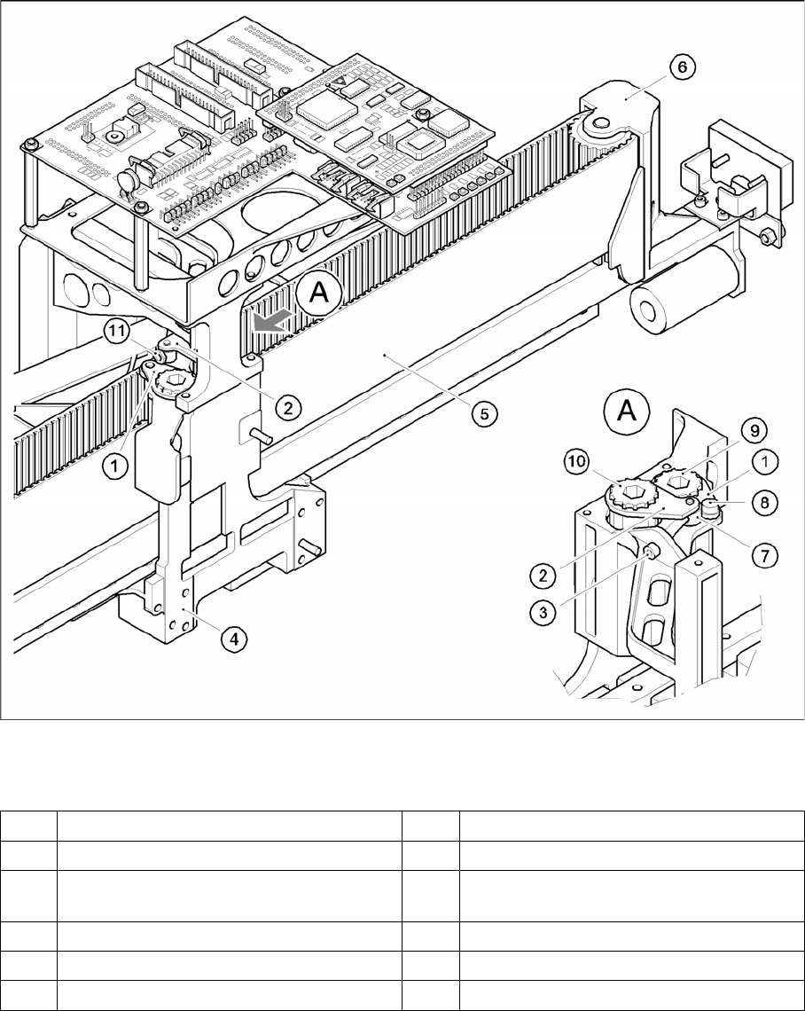
Replacing the tensioning keys
Legend
1 Tensioning key [00329478-01] 7 Spacer bolt with Benzing U-clip
2 Tensioning key [00329485-01] 8 M4 x 5 hexagon socket-head screw
3 M4 x 35 hexagon socket-head screw for
tensioning the toothed belt
9 Synchronizing disk, short
4 Head mount 10 Synchronizing disk, long
5 Toothed belt for the X-axis 11 Locknut
6 Deflection pulley
Service Work
Gantry 4.2.6 Replacing the Deflection Unit [00330938-02]
64 Service Manual SIPLACE D4/D4i
4.2.5.4
4.2.5.4 Installing the tensioning keys
Installing the tensioning keys
4.2.5.5
4.2.5.5 Settings
Settings
4.2.6
4.2.6 Replacing the Deflection Unit [00330938-02]
Replacing the Deflection Unit [00330938-02]
4.2.6.1
4.2.6.1 Tools and Equipment
Tools and Equipment
▪ Set of DIN 911 Allen keys
▪ Belt tension measuring device TSM [00326015-01]
▪ "Measuring belt tensions" operating instructions
4.2.6.2
4.2.6.2 Parts
Parts
▪ Deflection unit X [00330938-02]
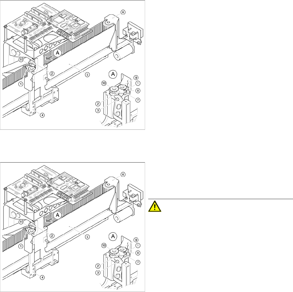
Replacing the tensioning keys
Installing the tensioning key, item 1 (synchronizing disk,
short)
► Place the tensioning key on the "short synchronizing
disk" (9).
► Fasten the tensioning key with the M4 x 5 hexagon
socket-head screw (8).
Installing the tensioning key, item 2 (synchronizing disk,
long)
► Use the Benzing U clip to fit the spacer bolt (7) onto
the new tensioning key.
► Place the tensioning key on the "long synchronizing
disk" (10).
► Use the size 8 Allen key to turn the synchronizing disk
slightly until the hexagon socket-head screw (3) can
be screwed in.
► Pretension the toothed belt by turning the hexagon
socket-head screw clockwise.
Replacing the tensioning keys
► Push the head mount towards the X-axis motor as far
as the stop on the elastomeric spring.
► Turn the hexagon socket-head screw to set the belt
tension to 53 Hz + 1/3 Hz.
CAUTION! Do not overstretch the toothed belt
when adjusting the belt tension.
► Secure the hexagon socket-head screw (3) with the
locknut (11).