SIPLACE D4-D4i 工程师手册_EN.pdf - 第102页
Service Work Component Handling 4.3.2 Cutter 102 Service Manual SIPLACE D4/D4i ► Turn the machine and then the flow of compressed air ON. ► Disconnect the movable changeover ta ble from the machine and mo ve it out of th…
Service Work
4.3.2 Cutter Component Handling
Service Manual SIPLACE D4/D4i 101
4.3.2.9
4.3.2.9 Exchanging the Control Unit
Exchanging the Control Unit
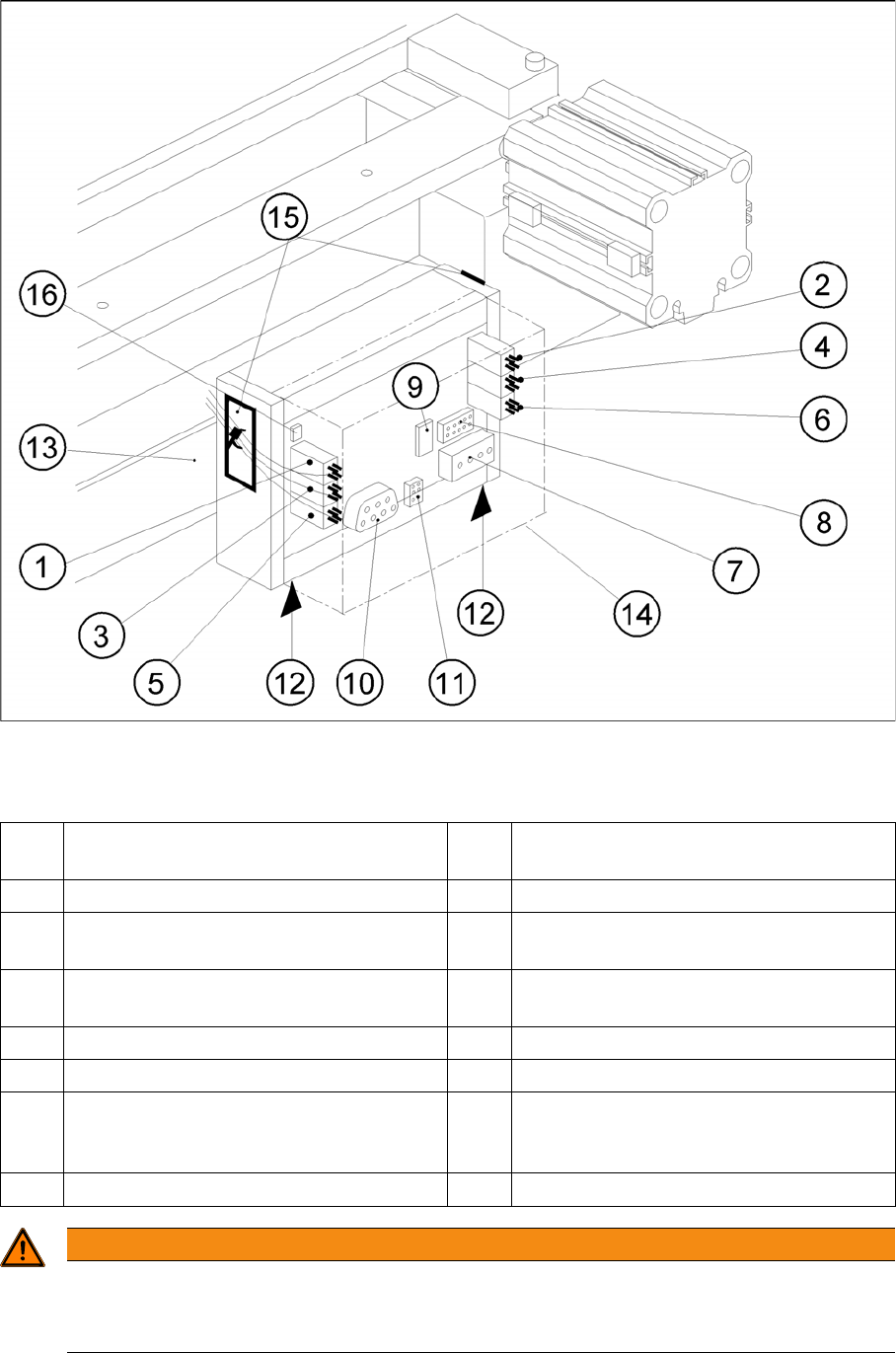
Exchanging the Control Unit, Allocation of the Plug-and-Socket Connections
Legend
The cutter remains installed in the machine.
1 Drive of solenoid valve for cylinder 2 (left) 9 Service plug (to be used exclusively by Sie-
mens)
2 Drive of solenoid valve for cylinder 1 (right) 10 CAN Bus
3 to the proximity switch on cylinder 2,
FRONT
11 Voltage supply
4 to the proximity switch on cylinder 1,
FRONT
12 Spring-mounted elements to disconnect
the control board box
5 to the proximity switch on cylinder 2, BACK 13 Support bar
6 to the proximity switch on cylinder 1, BACK 14 Cover
7 Cutter power supply (only busy on S-23
and F5)
15 Fixing pedestal adhesive type (LH and RH)
with cable tie Relieve tensile stress on ca-
ble/plug-and-socket connections.
8 Drive of cutter (only busy on S-23 and F5) 16 Coding plug
WARNING
Risk of injury!
There is a high risk of injury from the blades and the tape deflector.
Never reach into the cutter from below or into the empty-tape duct from above.
Service Work
Component Handling 4.3.2 Cutter
102 Service Manual SIPLACE D4/D4i
► Turn the machine and then the flow of compressed air ON.
► Disconnect the movable changeover table from the machine and move it out of the machine.
► Turn the machine OFF,
► Remove the cover from the control board.
► Carefully undo the cable ties (15) (left and right) on the outside of the control board box.
⇨ -> Do not damage the cables in this process.
► Mark the allocation of all press-fit connections and disconnect all press-fit connections from the con-
trol board.
► Disconnect the control unit (box) from the support bar by pushing both of the spring-mounted ele-
ments away from the ba.
► Carefully insert the new control unit onto the rail, in the correct rotary position and location, until it
locks into place.
See also
4.3.2.14 Final Steps [ ➙ 107]
4.3.2.10
4.3.2.10 Exchanging the Solenoid Valve on Left or Right (and/or Cable)
Exchanging the Solenoid Valve on Left or Right (and/or Cable)
► Turn the machine and then the flow of compressed air ON.
► Disconnect the movable changeover table from the machine and move it out of the machine.
► Switch off the supply of compressed air to the compressed air unit and actuate the needle valve on
the compressed air unit to bleed the compressed air lines.
► Turn the machine OFF and disconnect it from the mains supply.
Control Unit
► Mount an adhesive fixing pedestal for cable ties on
the outside LH and RH side of the control board box .
► Restore all press-fit connections in the correct alloca-
tion (see above).
► Use a cable tie to fasten the cables running to the LH
and RH side of the cable duct to the fixing pedestal
(on control board box). Make sure the cables and
press-fit connections are not subjected to strain.
► Place the cover back on the control board.
► Perform the appropriate “Final Steps”.
WARNING
There is a high risk of injury from the blades and the tape deflector.
Never reach into the cutter from below or into the empty-tape duct from above.
NOTICE
The cutter remains installed in the machine.
Service Work
4.3.2 Cutter Component Handling
Service Manual SIPLACE D4/D4i 103
If the cable of the solenoid valve is faulty:
► Carefully undo the relevant cable ties (left or right) on the outside of the control board box(10).
⇨ -> Do not damage the cables in this process.
► Remove the cover from the control board (9).
► Unplug the press-fit connection for the "control board for tape cutter - valve" cable of the appropriate
solenoid valve at the control board.
► Unplug the press-fit connection for the "control board for tape cutter - valve" cable at the appropriate
solenoid valve.
► Remove the cover from the cable duct (5).
► Remove the cable and run the new "control board for tape cutter - valve" cable.
⇨ Push the excess lengths of cable into the cable duct.
► Reconnect the press-fit connections at the correct points on the board and solenoid valve.
► Refit the cover on the control board (9).
► Install the cover on the cable duct (5).
► Use a cable tie to fasten the cables running to LH and/or RH side of the cable duct to the fixing ped-
estal (on control board box).
⇨ Make sure the cables/press-fit connections are not subject to strain (8).
► Perform the "Final Steps".
If the solenoid valve is faulty:
► Undo the 2 compressed air connections on the one-way restrictors at the faulty solenoid valve
(1,2,6).
► Unplug the press-fit connection for the "control board for tape cutter - valve" cable at the defective
solenoid valve (11).
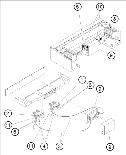
Exchanging the Solenoid Valve
Legend
1. Solenoid valve for cylinder 1, incl. mounting strap
2. Solenoid valve for cylinder 2, incl. mounting strap
3. to the plug-and-socket connection of the appropriate
solenoid valve
4. Screws for fastening the solenoid valve: 2 socket hex
head cap screws each, M3 x 6
5. Cover of the cable duct
6. Compressed air hoses for cylinder 1
7. Compressed air hoses for cylinder 2
8. Make sure there is not strain on the cables and press-
fit connections!
9. Cover
10. Fixing pedestal, adhesive type, with cable tie (LH and
RH)
11. Plug-and-socket connection on the solenoid valve