SIPLACE D4-D4i 工程师手册_EN.pdf - 第112页
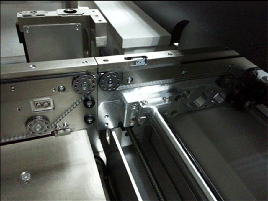
Service Work PCB conveyor system 4.4.1 Tools 112 Service Manual SIPLACE D4/D4i Non-modular conveyor, fixed rail See also 2.1 Safet y Instruction s [ ➙ 13] 4.4.1 4 . 4 . 1 T o o ls Tools ▪ Set of open-ended wre nches …

Service Work
4.3.2 Cutter PCB conveyor system
Service Manual SIPLACE D4/D4i 111
2. Non-modular PCB conveyor system with fitting the movable rail for width adjustment
Non-modular conveyor, movable rail
Service Work
4.4.2 Replacing the Complete Drive Unit [00359284] PCB conveyor system
Service Manual SIPLACE D4/D4i 113
4.4.2
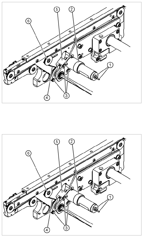
4.4.2 Replacing the Complete Drive Unit [00359284]
Replacing the Complete Drive Unit [00359284]
Overview
Removal
Legend
1. Cable connections
2. Heat-shrinkable sleeve
3. Fastening screws
4. Conveyor toothed belt
5. Motor mount
6. Deflection pulley with slot
The DC geared motors, including the motor mounts of all
5 conveyor areas, are of like construction. Please bear in
mind the following differences during assembly and dis-
assembly:
▪ The motor mount is installed at an angle (tilted), ac-
cording to the requirements of the installation site.
► Move the conveyor system apart until the motor fix-
ture screws (3) are accessible. This may differ ac-
cording to the conveyor type and area.
► Move the Y gantries into the area outside the PCB
conveyor.
► Switch off the machine and secure it to prevent unau-
thorized reactivation.
► Mark the polarity (+ / -) of the cable connections (1) -
important for the direction of rotation!
► Disconnect the cable shoes from the motor terminals
(1).