SIPLACE D4-D4i 工程师手册_EN.pdf - 第129页
Service Work 4.4.11 Replacing the Stepping Motor of the Width Adjustment Syst em [00367174] PCB conveyor system Service Manual SIPLACE D4/D4i 129 Removal/Installation See also 6.5.1 Adju sting the Ten sion of the Con…
Service Work
PCB conveyor system 4.4.11 Replacing the Stepping Motor of the Width Adjustment System [00367174]
128 Service Manual SIPLACE D4/D4i
Installation and adjustment
4.4.11
4.4.11 Replacing the Stepping Motor of the Width Adjustment System [00367174]
Replacing the Stepping Motor of the Width Adjustment System [00367174]
Overview
► Insert and twist the new stabilizer (5) until the plunger
just touches the actuator (1), so that the lifting table
can be gently moved upwards.
► Using the torque wrench:
Secure this position with the locknut (2) tightened to
8Nm.
► Check whether the stabilizer has been fixed onto the
mounting block with the locknut and that the stabilizer
plunger has a gap of approx. 0.1 mm to the actuator
(gap in untriggered mode). In this default setting, the
lifting table should move up gently.
► If this is not the case, loosen the locknut and turn the
stabilizer approx. one rotation into the mounting
block.
► Fit the lifting table plate.
► Start SITEST and move the lifting table up.
► The lifting table should move up gently i.e. you should
not hear the PCB clamping device audibly locking
into place and no clamping device error messages
should be issued.
► Check the speed of the lifting table cylinder and cor-
rect where necessary.
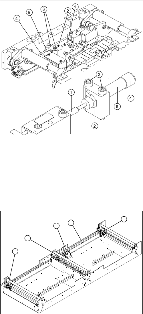
Legend
1. Width adjustment stepping motor
2. Toothed belt for the drive
3. Adjustment units 1, 2 and 3
3
3
1
3
2
Service Work
4.4.11 Replacing the Stepping Motor of the Width Adjustment System [00367174] PCB conveyor system
Service Manual SIPLACE D4/D4i 129
Removal/Installation
See also
6.5.1 Adjusting the Tension of the Conveyor Toothed Belt [ ➙ 224]
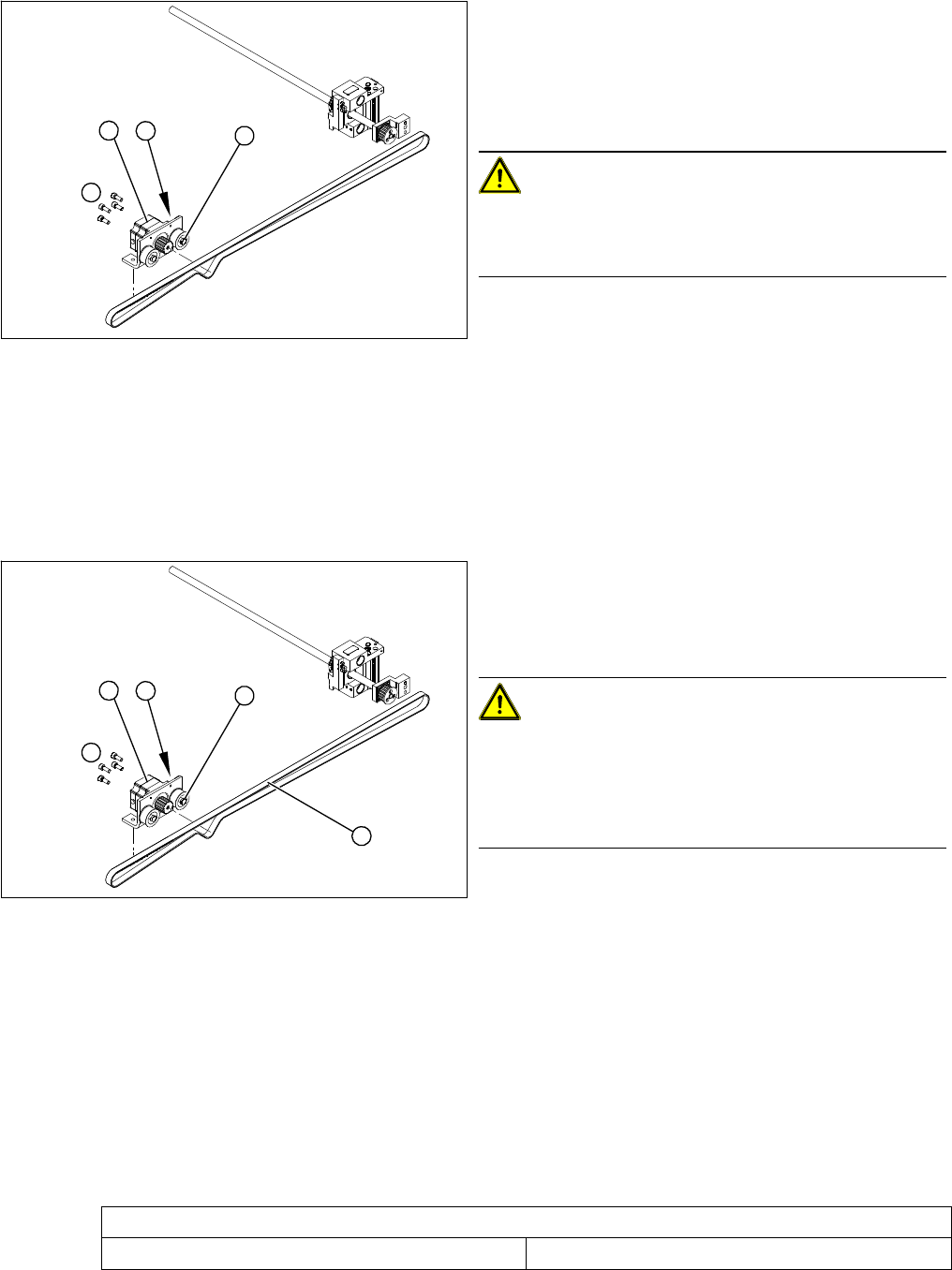
Legend
1. Loosening the eccentric axle on the deflection pulley
2. Locknut on the eccentric axle
3. Fastening screws for stepping motor
4. Stepping motor
CAUTION! Do not damage the toothed belt!
During the following removal and installation of the motor,
the toothed belt for the width adjustment drive must not
be stretched or kinked!
► Move the PCB conveyor to the position which gives
you best access to the stepping motor of the width
adjustment system.
► Move the Y gantries into the area outside the PCB
conveyor.
► Switch off the machine and secure it to prevent unau-
thorized reactivation.
4
1
3
2
► Loosen the screws fastening the lifting table plate and
remove the lifting table plate from the lifting table unit.
► Loosen the eccentric axis (1) on the deflection pulley
and relieve the tension on the drive toothed belt (5).
CAUTION! Toothed belt must not come off!
When relaxing the toothed belt, make sure the belt does
not come off (skip) the toothed disks at the 3 adjustment
units. This would cause incorrect alignment of the adjust-
ment units. Secure these positions with a suitable tool
(screw clamp etc.)
► Remove the 4 fastening screws (3) and then lift out
the stepping motor (4).
► Unplug the connection cable in the cable duct.
► Fit the new stepping motor and reconnect the system
to the electrical system.
► Tension the drive toothed belt.
Position the measuring point of the belt tension de-
vice at the strand center (i.e. the longest distance be-
tween two toothed disks) of the conveyor toothed
belt.
► Set the tension of the drive toothed belt according to
the following values.
4
5
1
3
2
Belt tension - width adjustment
Toothed belt for the drive 24 Hz +/- 2 Hz
Service Work
PCB conveyor system 4.4.12 Replacing the Limit Switch for the End Position Width Adjustment System
130 Service Manual SIPLACE D4/D4i
4.4.12
4.4.12 Replacing the Limit Switch for the End Position Width Adjustment System [00365108-xx]
Replacing the Limit Switch for the End Position Width Adjustment System [00365108-
xx]
Parts
▪ Limit switch on the assembly tray [00365002-xx]
▪ Limit switch for width adjustment 1 [00365108-xx]
▪ Limit switch for width adjustment 2 [00365109-xx]
▪ Limit switch for width adjustment - on the conveyor side [00362345-xx]
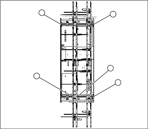
Overview
Legend
1. Limit switch 1 for width adjustment system of the ad-
justment unit
2. Limit switch for width adjustment system (for side)
3. Limit switch for assembly tray (for side)
4. Limit switch 2 for width adjustment system of the ad-
justment unit
Limit switch on the input conveyor:
In the vicinity of the input conveyor there are 4 limit
switches under the conveyor sides. The limit switch is de-
signed to prevent the conveyor sides hitting one another
or the conveyor base.
Limit switch on the output conveyor:
There are 2 limit switches for the adjustment unit in the vi-
cinity of the output conveyors. They serve to secure the
transport area and to initialize the adjustment unit during
width adjustment.
2
1
4
3
2