SIPLACE D4-D4i 工程师手册_EN.pdf - 第141页
Service Work 4.5.1 Replacing the C&P12 Head (D4) C &P12 Placement Head Service Manual SIPLACE D4/D4i 141 4.4.18.5 4 . 4 . 1 8 . 5 E x t e n s io n C o n t r o lle r B o a r d T S P 3 0 1 E f o r D u a l C o n v e…
Service Work
PCB conveyor system 4.4.18 Overview of the Electrical Components
140 Service Manual SIPLACE D4/D4i
4.4.18.2
4.4.18.2 Conveyor Conversion Board [00359425]
Conveyor Conversion Board [00359425]
Overview
4.4.18.3
4.4.18.3 Lifting Table Conversion Board [00362766]
Lifting Table Conversion Board [00362766]
Overview
4.4.18.4
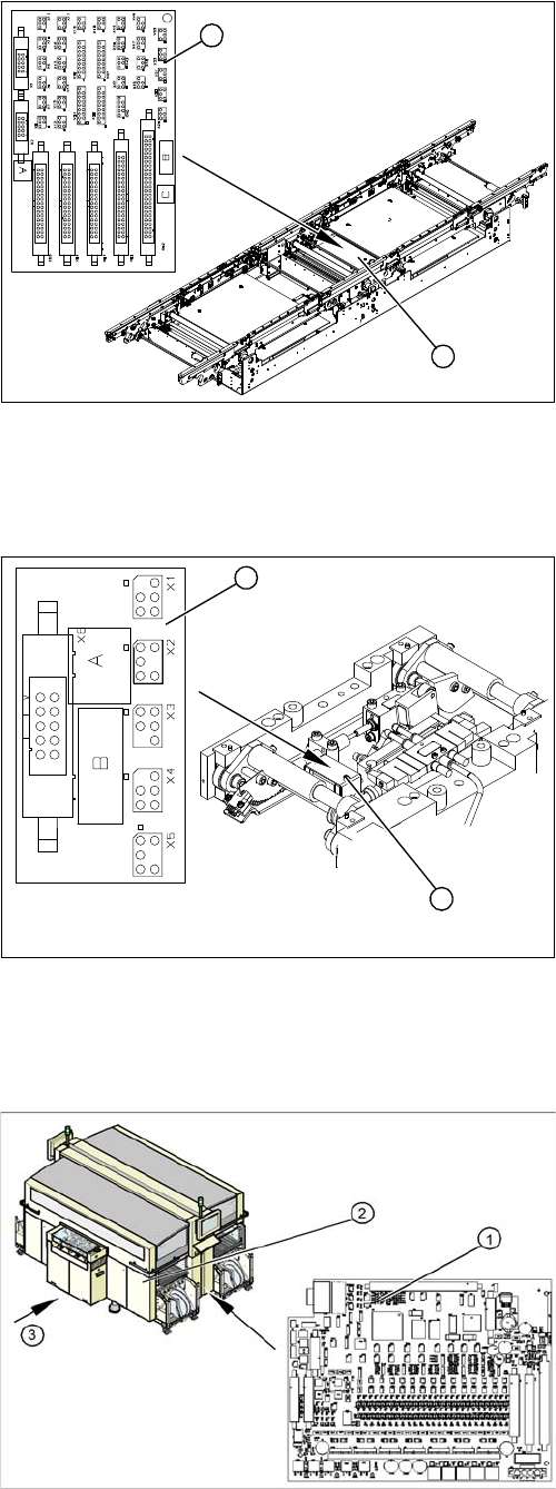
4.4.18.4 Conveyor Control TSP 301 [00370397]
Conveyor Control TSP 301 [00370397]
Overview
Legend
1. Conveyor conversion board
2. Cover
The conveyor conversion board (1) is situated in the vi-
cinity of the intermediate conveyor, under the cover (2).
For terminal assignment details, please refer to the cur-
rent version of the circuit diagram folder.
1
2
Legend
1. Lifting table conversion board
2. Cover
The lifting table conversion board (1) is situated on the
lifting table unit, under the cover (2).
For terminal assignment details, please refer to the cur-
rent version of the circuit diagram folder.
1
2
Legend
1. Conveyor Control TSP 301
2. Access to conveyor control
3. Transport direction
The conveyor control TSP 301 (1) is located in the sector
distributor 1 (2). The conveyor control is secured with a
screw-off cover.
For terminal assignment details, please refer to the cur-
rent version of the circuit diagram folder.
Service Work
4.5.1 Replacing the C&P12 Head (D4) C&P12 Placement Head
Service Manual SIPLACE D4/D4i 141
4.4.18.5
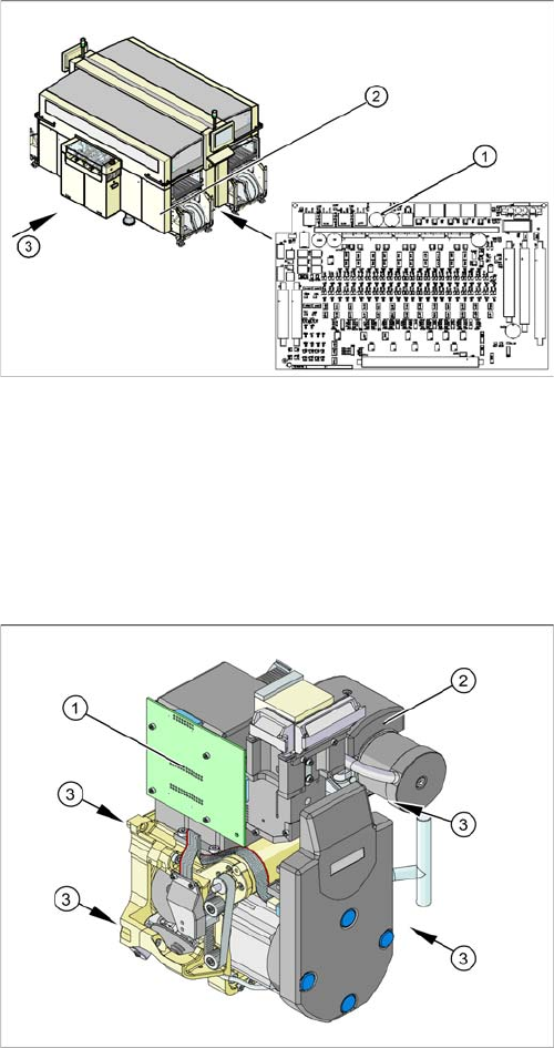
4.4.18.5 Extension Controller Board TSP 301E for Dual Conveyors [00370398]
Extension Controller Board TSP 301E for Dual Conveyors [00370398]
Overview
4.5
4.5 C&P12 Placement Head
C&P12 Placement Head
4.5.1
4.5.1 Replacing the C&P12 Head (D4)
Replacing the C&P12 Head (D4)
Overview
Legend
1. Conveyor control TSP 301E
2. Access to conveyor control
3. Transport direction
The extension card for the dual conveyor TSP 301E (1)
is located in the sector distributor 1 (2). The conveyor
control is secured with a screw-off cover.
For terminal assignment details, please refer to the cur-
rent version of the circuit diagram folder.
Legend
1. Illumination controller
2. Vacuum generator
3. 4 x fastening screws
Item number
▪ C&P head DLM3 with 12 segments [03041228-xx]
(C&P12 head)
Service Work
C&P12 Placement Head 4.5.1 Replacing the C&P12 Head (D4)
142 Service Manual SIPLACE D4/D4i
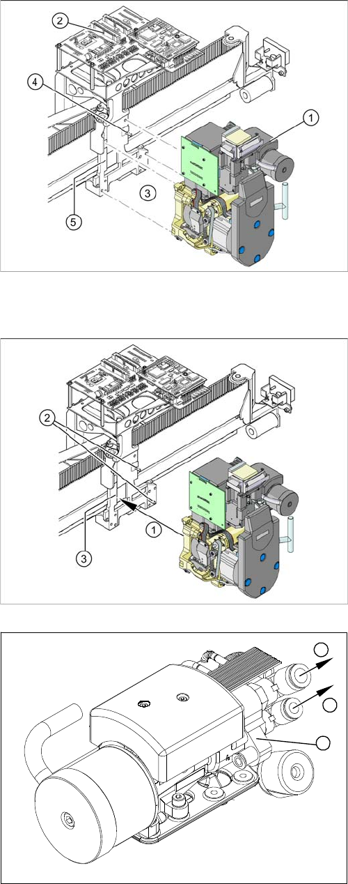
Removal
Installation
See also
6.3.1 Calibrating the C&P Head and Cameras [ ➙ 206]
► Remove the compressed air hoses from the pneu-
matic coupling of the pneumatic distributor (1).
► Loosen the press-fit connection to the head board (2)
from the C&P head.
► Loosen the 4 screws (3) fastening the C&P head.
► Carefully pull the C&P head off the parallel pins (4) on
the head mount (5) and remove the head from the
machine.
► Carefully move the C&P head towards the head plate
(3).
► Make sure that the parallel pins (2) on the head
mount slide into the holes drilled into the back part of
the C&P head.
► Carefully push the C&P head towards the head plate
until it lies flat against it.
► Fix the C&P head with the 4 screws provided (1).
► Connect the compressed air hoses (1) to the pneu-
matic coupling on the pneumatic distributor (2).
► Reconnect to the electricity system.
► Use the SITEST program to calibrate the C&P head.
1
1
2