SIPLACE D4-D4i 工程师手册_EN.pdf - 第145页
Service Work 4.5.2 Removal/Installation of Head Front Part C&P12 Placement Head Service Manual SIPLACE D4/D4i 145 Installation ► Grease the O-rings o f the vacuum d istributor with Unisilikon. ► Push the small O-ring…
Service Work
C&P12 Placement Head 4.5.2 Removal/Installation of Head Front Part
144 Service Manual SIPLACE D4/D4i
► Switch off the machine and secure it to prevent unauthorized reactivation.
► X series/SX4/DX4: Unplug the connection cable from the sockets in the head adapter and Vision dig-
ital.
► DX1/DX2: Unplug the connection cable from the sockets in the base adapter and Vision digital..
► Remove the compressed air hose for the air blast.
► DLM3 only: If required, loosen the screws fastening the C&P12 component sensor option. Observe
the assembly instructions "component sensor" [00193356-xx].
► Loosen the four screws fastening the front part of the head.
► Pull the front part of the C&P head off the parallel pins on the back part and place it on a clean, soft
and ESD-proof surface.
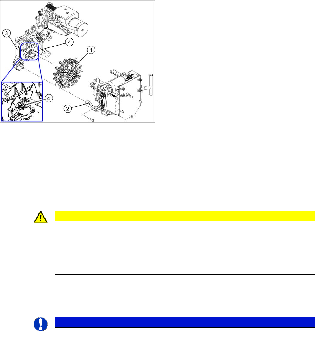
► You will find the vacuum distributor block loose (unconnected) on the back part of the machine. Re-
move this vacuum distributor block.
1. Star
2. Front part
3. Back part
4. Vacuum distributor block
CAUTION
Keep hold of the placement head and make sure the star position is correct!
► When you undo the last screw, hold the C&P head so that it does not accidentally drop off
the back part.
► When you remove the front part of the C&P head, make sure that the star is rotated roughly
30° or 15° out of the vertical sleeve position. If not, the valve plunger will remain attached
to the valve adjustment drive.
NOTICE
Vacuum distributor block
The vacuum distributor block is normally clamped between the front and back parts of the ma-
chine and transmits the vacuum for the holding circuit.
Service Work
4.5.2 Removal/Installation of Head Front Part C&P12 Placement Head
Service Manual SIPLACE D4/D4i 145
Installation
► Grease the O-rings of the vacuum distributor with Unisilikon.
► Push the small O-ring onto the tube.
► Place the large O-ring on the vacuum distributor block.
► Check that the O-rings are seated correctly.
► Insert the distributor block into the back part.
► Make sure that all contact surfaces and pins are clean.
► Place the front part on the back part so that the parallel pins are aligned with the holes in the front
part.
► Carefully push the front part against the back part until it lies flat against the back part.
► Tighten the four fastening screws.
► Reconnect to the electrical and compressed air systems.
► If necessary, fit the C&P 12 component sensor option. Make sure that there is a 1 mm distance from
the component sensor housing to the back of the placement head housing. Observe the assembly
instructions "component sensor" [00193356-xx].
► Calibrate the C&P head with the help of the station software.
See also
6.3.1 Calibrating the C&P Head and Cameras [ ➙ 206]
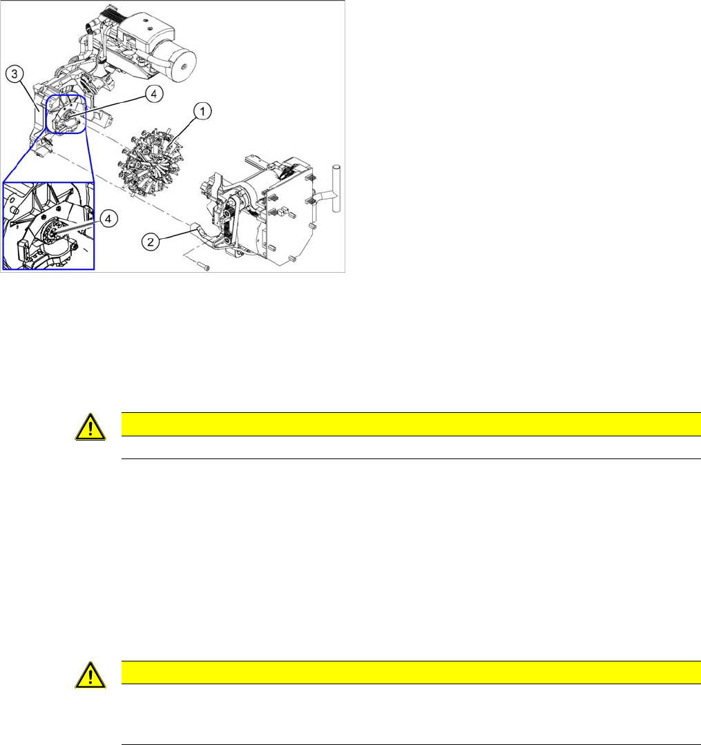
1. Star
2. Front part
3. Back part
4. Vacuum distributor block
CAUTION
Star position 15°!
CAUTION
Check how the cables are run!
Make sure that the folded part of the ribbon cable for the "Z axis up" light barrier is pushed back
under the illumination board.
Service Work
C&P12 Placement Head 4.5.3 Replacing the Component Camera (D Series) [03014449-xx]
146 Service Manual SIPLACE D4/D4i
4.5.3
4.5.3 Replacing the Component Camera (D Series) [03014449-xx]
Replacing the Component Camera (D Series) [03014449-xx]
Removal/Installation
Installation
See also
4.5.22 Press Fit Connections with Fixture Clips on the Vision Board (D Series) [ ➙ 184]
The component camera must be replaced as a complete
unit. This consists of the lens system, camera, amplifier,
illumination planes and "illumination controller" board.
Article numbers
▪ SST28 [03014449-xx]
▪ SST29 [03018637-xx]
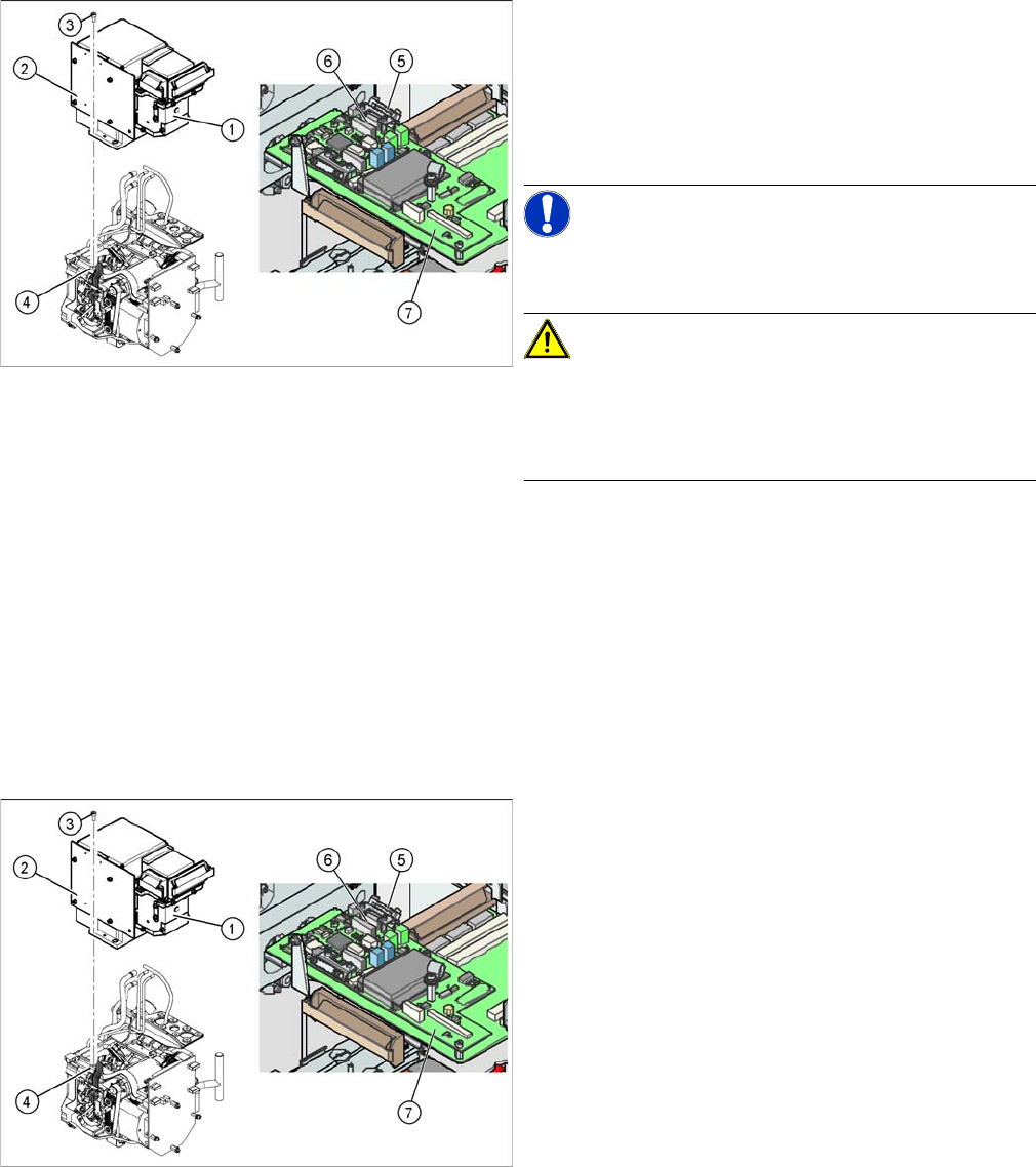
NOTICE! You may need to completely disman-
tle the front part of the head (4), so that the components
can be more easily accessed.
CAUTION! Do not damage the fixture clips!
To disconnect the component and PCB camera connec-
tions, you need to open the fixture clips by applying pres-
sure to the side of the connector.
For details see section xxx
► Disconnect the flat ribbon cable holders (5) at the Vi-
sion board (7) of the gantry head distributor.
► Pull both flat ribbon cable connectors (6) off the Vi-
sion board of the gantry head distributor (2).
► Loosen the four screws (3) holding the component
camera.
► Carefully lift off the component camera (1).
► Make sure that all contact surfaces are clean.
► Place the holes in the camera on the parallel pins (4).
► Carefully position the camera on the C&P head, until
the camera plinth lies flat on the contact surface of
the front part of the C&P head.
► Fix the camera in place with the four screws provided
(3).
► Fit the front part of the C&P head (4).
► Reconnect the flat ribbon cables (6) to the Vision
board (7) of the gantry head distributor.
► Refit the flat ribbon cable strain relief (5). This rees-
tablishes the ground connection.
► Start the machine.
► Use the SITEST program to calibrate the C&P head.