SIPLACE D4-D4i 工程师手册_EN.pdf - 第159页
Service Work 4.5.9 Replacing the Valve Positi oning Drive for the Reject C irc uit [00367768-xx] C&P12 Placement Head Service Manual SIPLACE D4/D4i 159 See also 6.3.1 Ca librating the C&P Head and C ameras [ …
Service Work
C&P12 Placement Head 4.5.9 Replacing the Valve Positioning Drive for the Reject Circuit [00367768-xx]
158 Service Manual SIPLACE D4/D4i
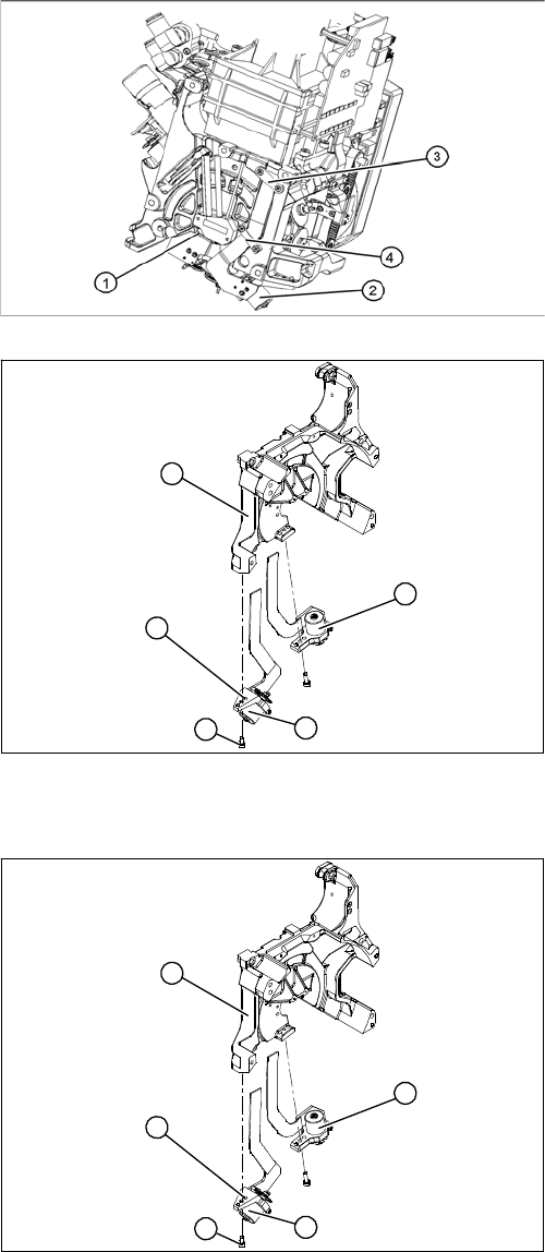
Removal
Installation
Legend
1. Valve positioning drive for the placement circuit
[00368075-xx]
2. Valve positioning drive for the reject circuit
[00367768-xx]
3. Flat ribbon cable clamp
4. Flat ribbon cable clamp
► Dismantle the C&P head.
► Loosen the two M2x6 Phillips screws on the flat rib-
bon cable clamp (3) and (4).
Legend
1. Valve positioning drive for the placement circuit
[00368075-xx]
2. Valve positioning drive for the reject circuit
[00367768-xx]
► Loosen the fastening screw (4).
► Carefully remove the valve positioning drive (2).
5
1
4
3
2
► Insert the valve positioning drive. Make sure that it is
seated correctly on the parallel pins (5).
► Loosely screw in the hexagon socket-head screw (4)
► Use the cable clamps to fix the ribbon cable in posi-
tion. Make sure that the ribbon cables are not
pinched.
5
1
4
3
2
Service Work
4.5.9 Replacing the Valve Positioning Drive for the Reject Circuit [00367768-xx] C&P12 Placement Head
Service Manual SIPLACE D4/D4i 159
See also
6.3.1 Calibrating the C&P Head and Cameras [ ➙ 206]
4.5.9.1
4.5.9.1 New Valve Positioning Drives (From Version 03)
New Valve Positioning Drives (From Version 03)
4.5.9.2
4.5.9.2 Mechanical Adjustment (Up To Version 02)
Mechanical Adjustment (Up To Version 02)
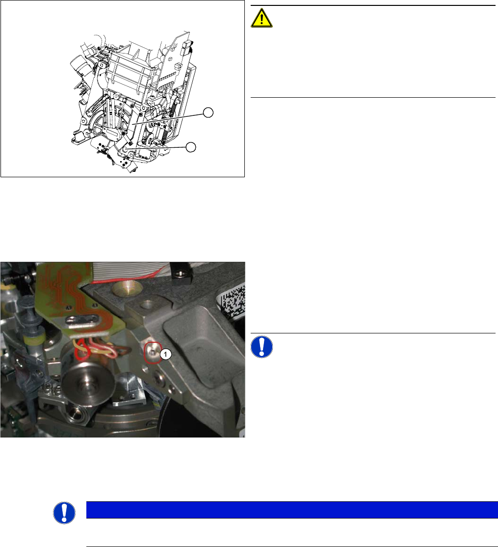
CAUTION! Check how the cables are run!
Check that the ribbon cables are laid correctly (1).
The flat ribbon cable for the two valve positioning units
must be run outside the holes (2). otherwise it will be
damaged when the C&P head is fitted onto the head
plate.
1
2
New valve positioning drive holder for the reject position
(DLM2/3) with position locking function
These valve positioning drives replace the previous ver-
sions on the DLM2/3 placement head.
For precise alignment and adjustment of the drives, use
the new tool which replaces the distance gauge 0.2 mm
[00325445-01].
NOTICE! This holder also fits the valve position-
ing drive on the placement and reject position of the
DLM1 placement head. A second 1.4 mm thread (1) is
provided on the opposite side for this purpose.
NOTICE
Instead of using the adjustment valve plungers, the DLM1 and DLM2 heads can also be set
with the distance gauge.
Service Work
C&P12 Placement Head 4.5.9 Replacing the Valve Positioning Drive for the Reject Circuit [00367768-xx]
160 Service Manual SIPLACE D4/D4i
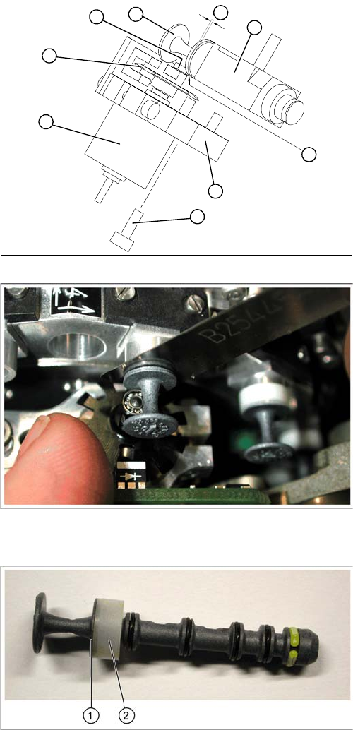
Legend
1. Stepping motor
2. Cam disk
3. Deep-groove ball bearings
4. Valve plunger
5. Valve casing
6. M3x10 hexagon socket-head screw
7. Valve positioning drive (flange)
► Use the feeler gauge to set the distance between the
valve plunger and valve casing to 0.2 mm (A).
► Turn the cam disk (2) until the deep-groove ball bear-
ings (3) point towards the valve casing.
► Move the valve positioning drive (7) so that the deep-
groove ball bearings (3) come into contact with the
valve plunger (4) at position (B).
► Use the hexagon socket-head screw to fix the adjust-
ment unit in this position (6).
► Fit the C&P head.
► Use the SITEST program to test that the valve posi-
tioning drive is functioning correctly.
► Use the SITEST program to calibrate the C&P head.
Valve plunger version 03
(C&P12: [00351498
-
03], C&P6: [00351500
-
03])
► If the new valve plungers are used (s. diag. on left)
proceed as follows:
⇨ Take out one valve plunger and remove the sleeve
(2).
⇨ Insert the plunger without bushing and carry out
the following steps on this segment:
► Insert the distance gauge (0.2 mm) between valve
plunger and valve casing.
► Rotate the valve positioning drive 90 degrees from its
initial position. The eccentric of the valve adjustment
drive will just touch the inner side (1) of the valve
plunger.
► Fix the motor of the valve drive in this position.
► Remember to replace the tube on the valve plunger.
B
A
1
7
6
5
4
3
2