SIPLACE D4-D4i 工程师手册_EN.pdf - 第162页
Service Work C&P12 Placement Head 4.5.9 Replacing the Valve Positioning Drive for the Reject Circuit [00367768-xx] 162 Service Manual SIPLACE D4/D4i ► Use a pointed obje ct t o car efully turn th e c am d isk s o tha…
Service Work
4.5.9 Replacing the Valve Positioning Drive for the Reject Circuit [00367768-xx] C&P12 Placement Head
Service Manual SIPLACE D4/D4i 161
4.5.9.3
4.5.9.3 Mechanical Adjustment (From Version 03)
Mechanical Adjustment (From Version 03)
Setting the valve positioning drive for the reject position
NOTICE
The valve positioning drives of the DLM1 and DLM3 head reject position can be set with the
adjustment valve plungers.
CAUTION
Even if your placement machine does not use the valve positioning drive for rejecting compo-
nents (rejection vertically down), the position of this drive must still be correct. If this is not the
case, an incorrectly set valve positioning drive could have a negative influence on the plunger
positions during the reference run and during star rotation.
► Fit the dismantled placement head onto the head
mount and place this down on the front or place the
placement head down on a soft, ESD conductible
surface on its front.
► The lockscrew (at the bottom side of the placement
head) and the fastening screw of the valve position-
ing drive need to be loosened or are only screwed in
slightly during assembly of the drive.
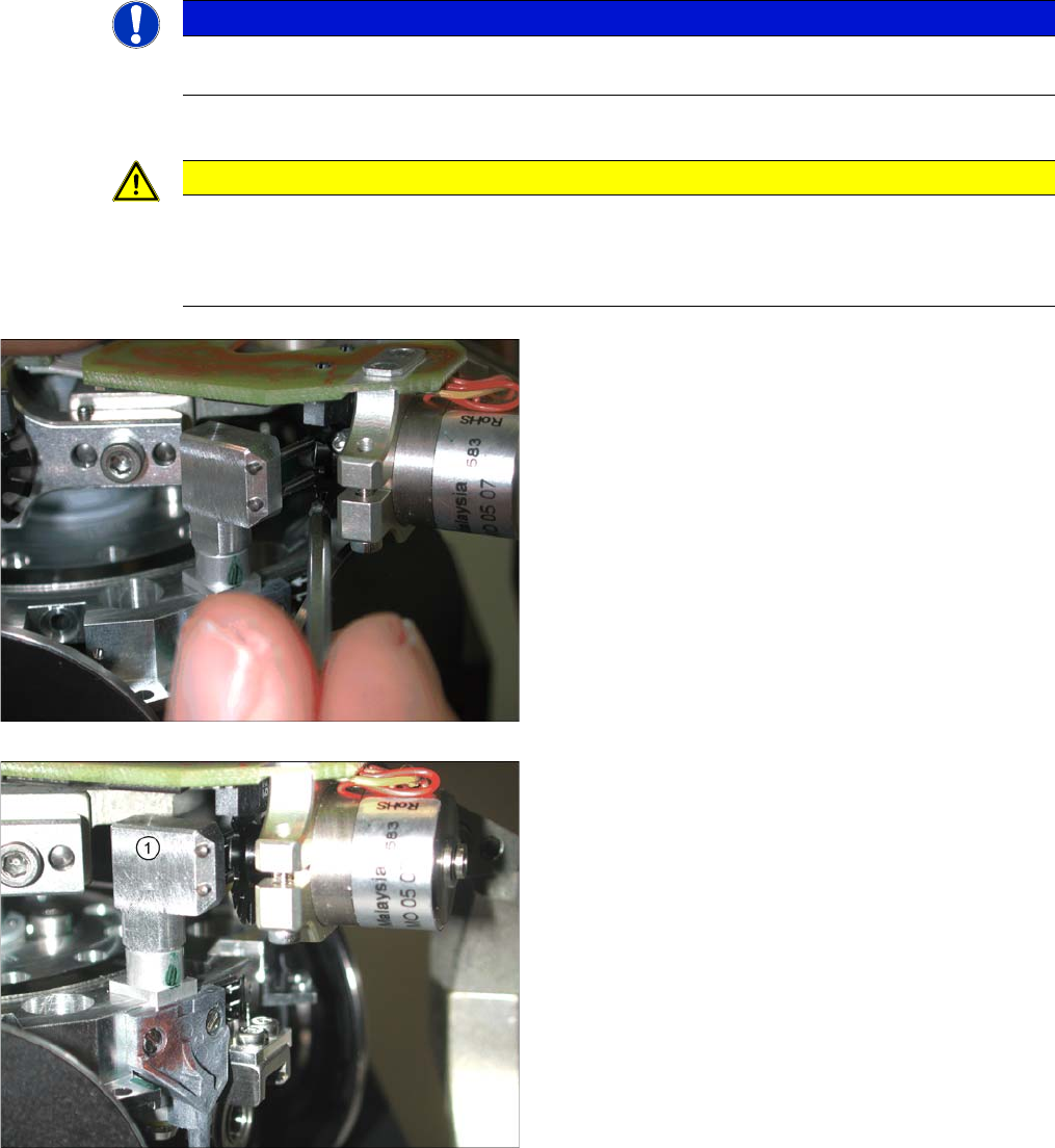
► Fit the adjustment valve plunger (1) in place of the
valve plunger, for the reject position (R) - as shown in
the diagram.
► Turn the adjustment valve plunger so that the tips of
the two centering pins are near to the cam disk be-
hind the ball bearing.
Service Work
C&P12 Placement Head 4.5.9 Replacing the Valve Positioning Drive for the Reject Circuit [00367768-xx]
162 Service Manual SIPLACE D4/D4i
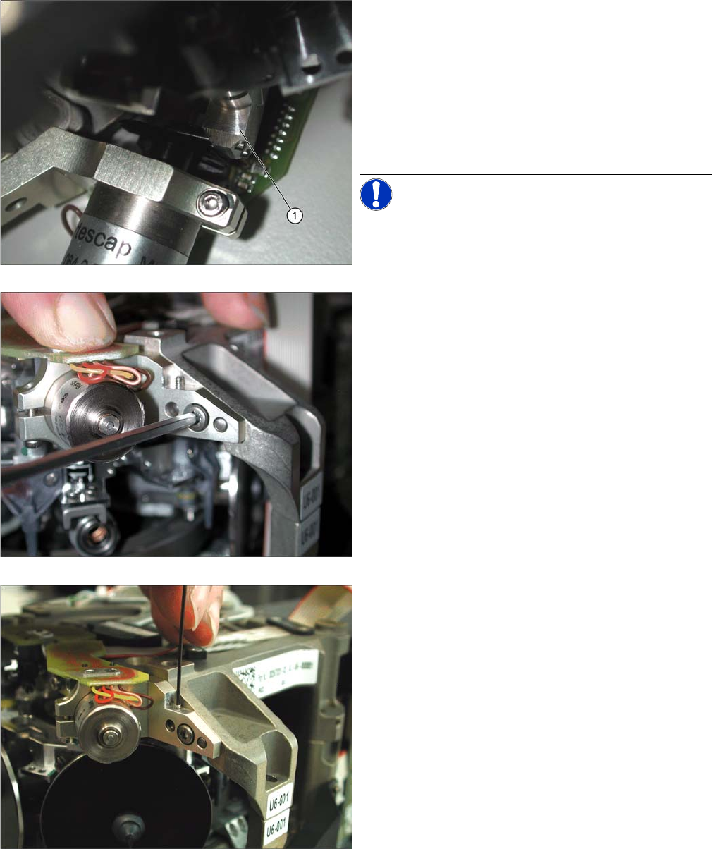
► Use a pointed object to carefully turn the cam disk so
that it is in the "starting position" (ball bearing horizon-
tally aligned next to the drive shaft).
► Carefully turn the placement star in the direction of
the valve positioning drive so that the two centering
pins behind the ball bearing grasp the fixtures on the
cam disk. The adjustment valve plunger (1) swivels
into the correct position (centering pins parallel to
cam disk).
NOTICE! As the cam disk of the reject valve po-
sitioning drive is behind the connection board, this setting
is slightly more complex than that for the placement cir-
cuit.
► Press the valve positioning drive in the direction of
the placement star and fasten the drive holder with a
2.5 mm Allen key.
► Now tighten the locking threaded pin with an Allen
key of size 0.89 mm. Press the valve positioning drive
against it. Do not tighten excessively as this could
push the valve positioning drive "backwards".
► Remove the adjustment plunger by turning the place-
ment star back and then rotating the adjustment
plunger out of the valve housing.
► Then replace the adjustment plunger with a plunger
and protection ring.
Service Work
4.5.10 Replacing the Light Barrier "Z Axis Up" [03053294-xx] C&P12 Placement Head
Service Manual SIPLACE D4/D4i 163
4.5.10
4.5.10 Replacing the Light Barrier "Z Axis Up" [03053294-xx]
Replacing the Light Barrier "Z Axis Up" [03053294-xx]
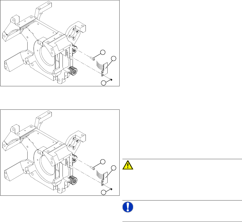
Removal
Installation
Legend
1. 2 x M2.0x4 hexagon socket-head screws
2. 2 Phillips screws
3. Light barrier board "Z axis up"
► Switch off the machine and secure it to prevent unau-
thorized reactivation.
► Remove the plug from the slot on the intermediate
distributor.
► Undo the two M2.0x4 hexagon socket-head screws
(1) and remove the ribbon cable clamp.
► Loosen the two M1.6x3 Phillips screws (2).
► Remove the light barrier "Z axis up"(3) with its cable.
1
3
2
► Use the two M1.6x3 Phillips screws (2) to fix the "Z
axis up" light barrier board (3). Move the board as far
upwards as the screws will tolerate.
► Connect the ribbon cable plug to the slot on the inter-
mediate distributor.
► Use the flat ribbon cable clamp and the two hexagon
socket-head screws (1) to fix the flat ribbon cables.
CAUTION! Check how the cables are run!
Make sure that the flat ribbon cable is not pinched in the
guide channel.Make sure that you push the folded part of
the flat ribbon cable for the "Z axis up" light barrier back
under the illumination board.
NOTICE! Shortened cable
A new version is available with a shortened flat ribbon.
1
3
2