SIPLACE D4-D4i 工程师手册_EN.pdf - 第170页
Service Work C&P12 Placement Head 4.5.15 Replacing the Forced Air Unit [0 0367 793-xx] 170 Service Manual SIPLACE D4/D4i Installation 4.5.15 4 . 5 . 1 5 R e p la c in g t h e F o r c e d A ir U n it [ 0 0 3 6 7 7 9 3…
Service Work
4.5.14 Replacing the Complete Z Axis [03001959-xx] C&P12 Placement Head
Service Manual SIPLACE D4/D4i 169
4.5.14
4.5.14 Replacing the Complete Z Axis [03001959-xx]
Replacing the Complete Z Axis [03001959-xx]
► Move the changeover table out of the machine.
► Switch off the machine.
► Remove the front part of the C&P head. (See "4.5.2
Removal/Installation of Head Front Part" [ ➙ 143].)
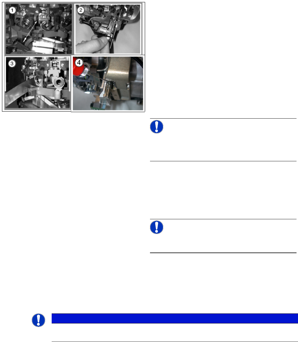
► (1) Dismantle the light barrier under the Z axis, by
loosening the two M1.6x3 DIN 84 screws.
► (2) Carefully pull the cable out of the cable duct until
it lies loosely.
► (3) Loosen the connection between the driver arm
and driver bracket by removing the two M2x14 DIN
912 screws.
► (4) Pull the driver arm, together with the centering pin,
out of the driver bracket and move the driver arm into
the stop position in the raceway.
► (5) Remove the three screws holding the Z axis in
place (2x M3x14, 1x M3x4).
NOTICE
Replacing the Z axis on the DLM3/DLM4
We recommend replacing the complete Z axis after approx. 100 million placements.
Service Work
C&P12 Placement Head 4.5.15 Replacing the Forced Air Unit [00367793-xx]
170 Service Manual SIPLACE D4/D4i
Installation
4.5.15
4.5.15 Replacing the Forced Air Unit [00367793-xx]
Replacing the Forced Air Unit [00367793-xx]
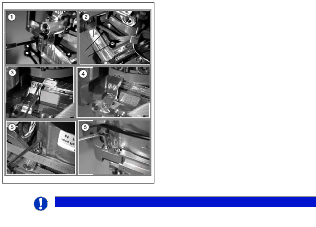
Removal
► (1) Rotate the star into the position shown and then
remove the Z axis from its guidance by taking hold of
the mounting plate.
Clean the contact surface with SIPLACE cleansing
tips and ethanol.
► (2) Push the new Z axis guide into the groove provid-
ed.
Press the reference edge (inner side) of the Z axis
into the groove and fix the Z axis with the screws pro-
vided.
► (3) Use the feeler gauge to check the gap between
the jaws and the side edges of the circular arc guide.
The gap may be between 0.02 and 0.03 mm.
Adjust the jaws if necessary.
Reassemble the placement head as follows.
NOTICE!
The board must be fitted centered to the jaws.
Make sure that the board does not rub against the frame
(check with gauge if necessary).
Complete the following step at every second service in-
terval for the head:
► (4) Use the mini oiler device to apply a small amount
of oil [00367071-xx] to the drilling provided.
Make sure that there is not too much oil coming out
of this hole.
NOTICE!
Where dirt is not excessive, the oil can be directly applied
to the rail.
Refit the front part of the C&P head. (See "4.5.2 Remov-
al/Installation of Head Front Part" [ ➙ 143].)
NOTICE
DLM 4
In DLM4, the hose for the reject circuit is cut off and the one-way restrictor is closed.
Service Work
4.5.15 Replacing the Forced Air Unit [00367793-xx] C&P12 Placement Head
Service Manual SIPLACE D4/D4i 171
Installation
See also
4.5.4 Replacing the Intermediate Distributor [ ➙ 147]
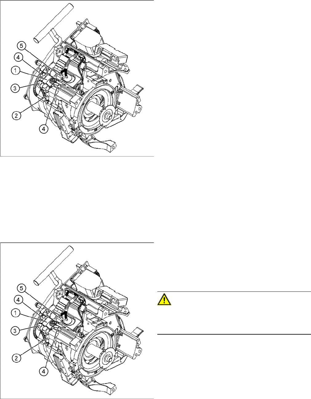
1. Forced air unit
2. To the "placement circuit" compressed air tube and
the compressed air sensor on the intermediate dis-
tributor
3. To the "reject circuit" compressed air tube
4. 2 M3x20 hexagon socket-head screws
5. SW8 union nut for the compressed air connection
► Move the changeover table out of the machine.
► Switch off the machine.
► Remove the cable plug from the slot on the interme-
diate distributor.
► Detach the black compressed air hose from the plug-
in coupling on the vacuum distributor.
► Dismantle the intermediate distributor.
► Detach the compressed air sensor.
► Detach the compressed air hose for the placement
position (2) from the "placement circuit" compressed
air tube.
► Detach the compressed air hose for the reject posi-
tion (3) from the "reject circuit" compressed air tube.
► Undo the 2 hexagon socket-head screws (4).
► Remove the forced air unit (1).
► Loosen the union nut (5) and detach the compressed
air supply hose.
► Reconnect the hoses.
► Fix the forced air unit (1) with the two hexagon sock-
et-head screws (4).
► Connect the plug to the slot on the intermediate dis-
tributor.
CAUTION!
Risk of injury!
Risk of injury from the compensating tube when the hose
is pushed onto the measuring tube!
► Fit the intermediate distributor.