SIPLACE D4-D4i 工程师手册_EN.pdf - 第176页
Service Work C&P12 Placement Head 4.5.18 Replacing the Star Drive 176 Service Manual SIPLACE D4/D4i ▪ When fitting the star, make su re that the silic one hoses are n ot pinched and/or damaged. 4.5.18 4 . 5 . 1 8 R e…
Service Work
4.5.17 Replacing the Star C&P12 Placement Head
Service Manual SIPLACE D4/D4i 175
4.5.17.2
4.5.17.2 Replacing the Air Blast Supply to the Star [03000896-xx]
Replacing the Air Blast Supply to the Star [03000896-xx]
Removal/installation
4.5.17.3
4.5.17.3 Replacing the Silicone Hoses on the Star [00341183S01]
Replacing the Silicone Hoses on the Star [00341183S01]
Removal
Installation
► Installation is performed by following the above instructions in the reverse order. Observe the follow-
ing points:
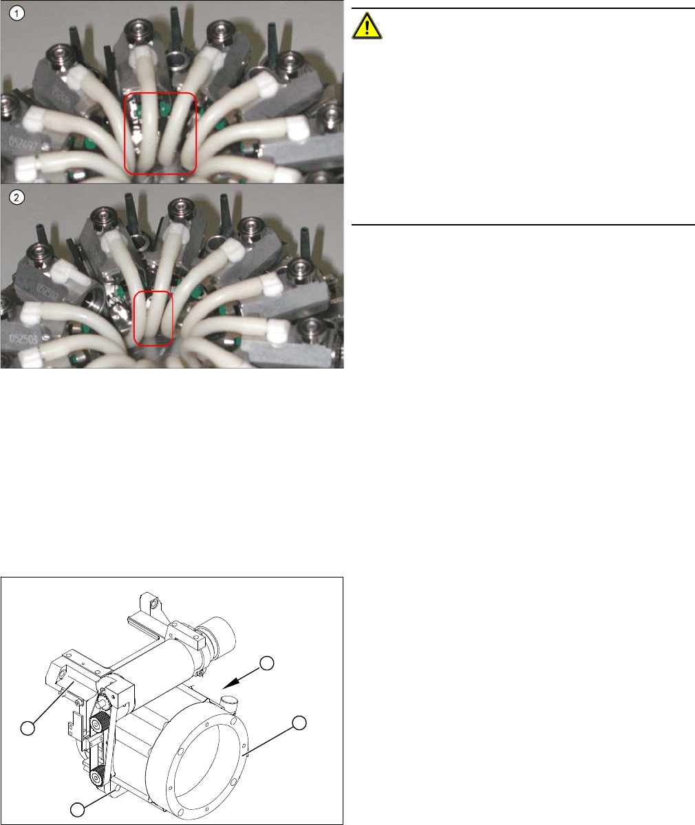
▪ Check that the white connection pieces are seated firmly on the segments. If these are loose, you
will need to replace the entire star.
▪ Make sure that there is an even space between the hoses:
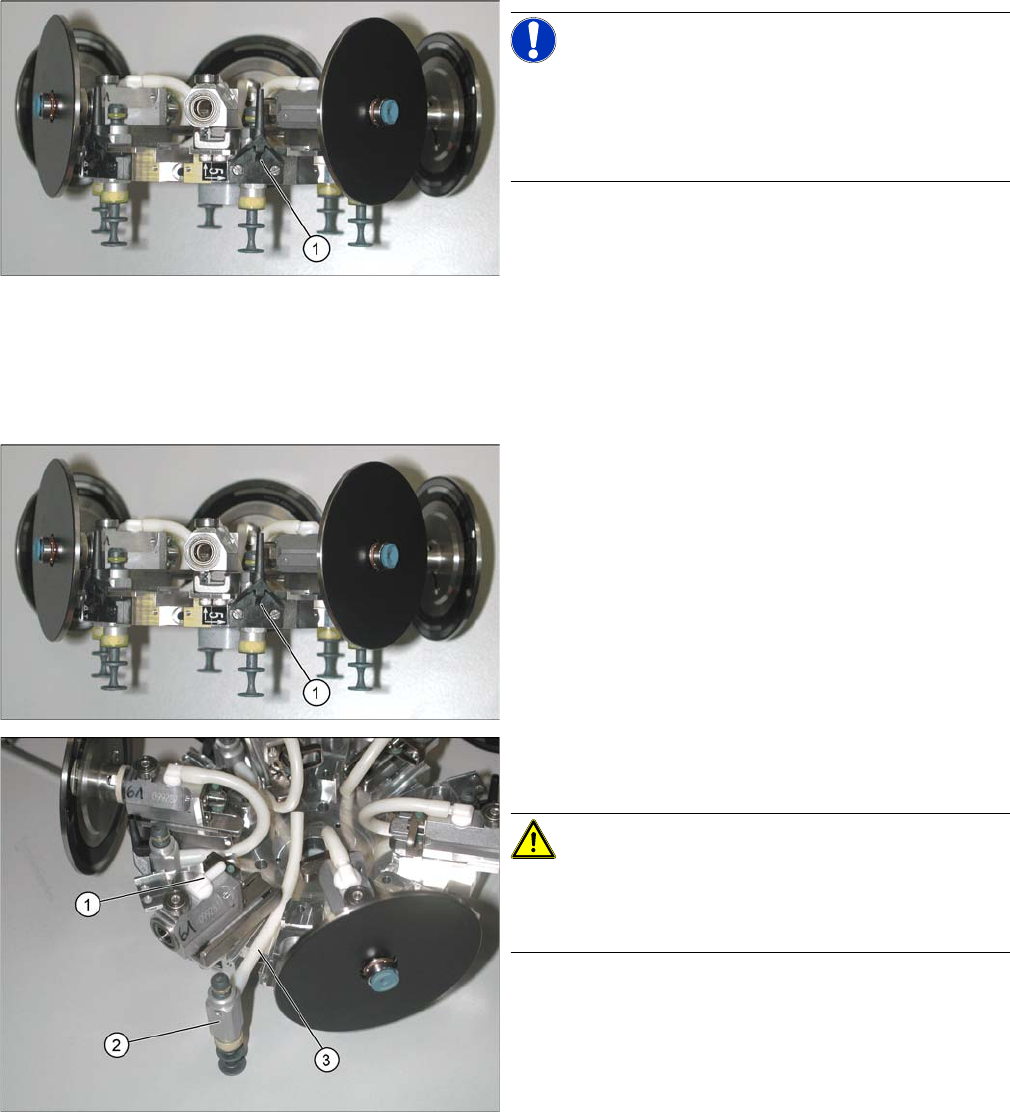
NOTICE!
Do not remove the star!
For clarity, the diagram shows the star when removed
from the machine. However, you do not need to remove
the star to replace the air blast supply.
► Undo and remove the two screws fastening the air
blast supply (1).
► Fasten the air blast supply with the two screws pro-
vided.
► Dismantle the star from the C&P head.
► Remove the sleeve from the segment of the defective
hose.
► Undo and remove the two screws fastening the air
blast supply (1).
► Disconnect the hose (3) from the segment (1).
► Now pull the valve (2) out of the star.
CAUTION!
O-ring
There is an O-ring behind the valve. Make sure that you
do not lose this and that you fit it again during installation!
► Disconnect the hose from the valve.
Service Work
C&P12 Placement Head 4.5.18 Replacing the Star Drive
176 Service Manual SIPLACE D4/D4i
▪ When fitting the star, make sure that the silicone hoses are not pinched and/or damaged.
4.5.18
4.5.18 Replacing the Star Drive
Replacing the Star Drive
Parts, equipment and tools
▪ Star motor assembly DLM1, DLM2 [03020626-xx]
▪ Star motor assembly DLM3, DLM4 [03031187-xx]
Removal
CAUTION!
If the connecting silicone hoses between the valve and
segment are replaced, make sure that they are not dam-
aged by rubbing against one another (2) .
To ensure this, make sure that the silicone hoses have
been cut to the exact length and that they are pushed
onto the respective connection pieces as far as possible
(up to the stopper).
Make sure that the hoses do not touch (1) one another.
Check the distance while pushing all segments all the
way in. Ideally, the distances should all be the same.
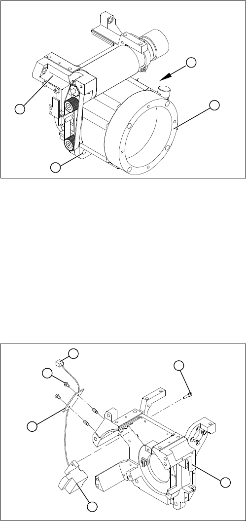
1. Star drive, digital (DLM3, DLM4)
2. 4 x M5x16 hexagon socket-head screws
3. Front section of C&P head
(A) Connecting cable for the star drive
► Dismantle the intermediate distributor.
► Dismantle the front part of the C&P head.
► Dismantle the star.
► Loosen the four M5x16 hexagon socket-head screws
(2).
► Lift the star drive off the front part of the C&P head.
A
1
3
2
Service Work
4.5.19 Replacing the RSF Digital Rotary Encoder (DP Axis) [00335990-xx] C&P12 Placement Head
Service Manual SIPLACE D4/D4i 177
Installation
See also
4.5.4 Replacing the Intermediate Distributor [ ➙ 147]
4.5.2 Removal/Installation of Head Front Part [ ➙ 143]
4.5.17 Replacing the Star [ ➙ 172]
6.3.9 Determining the Zero Point Correction for the Star Axis of the C&P Head [ ➙ 215]
4.5.19
4.5.19 Replacing the RSF Digital Rotary Encoder (DP Axis) [00335990-xx]
Replacing the RSF Digital Rotary Encoder (DP Axis) [00335990-xx]
Removal
► Place the star motor onto the front part of the C&P
head, so that the star drive connection cable points to
the position marked (A).
► Fix the star drive in place with the four M5x16 hexa-
gon socket-head screws (2).
► Fit and adjust the star. (See zero point correction.)
► If you are unable to adjust the zero point correction
correctly, loosen the 4 star motor screws and rotate
the star motor in the required direction, within the
tightening tolerance.
► Fit the front part of the C&P head.
A
1
3
2
1. Front section of C&P head
2. RSF digital rotary encoder 12/DLM3
3. 2 x M2.5x8 hexagon socket-head screws
4. RSF board, type 950
5. 2 x M2.5x4 hexagon socket-head screws
6. Plug connector in the slot on the intermediate distrib-
utor
► Dismantle the front part of the C&P head.
► Remove the black blanking cap over the RSF board
(4).
► Remove the plug connector (6) from the slot on the
intermediate distributor.
► Loosen the two M2.5x4 hexagon socket-head screws
(5) for fixing the RSF board.
► Dismantle the handle of the C&P head.
► Loosen the two M2.5x8 hexagon socket-head screws
(3) and remove the digital encoder.
1
6
5
4
3
2