SIPLACE D4-D4i 工程师手册_EN.pdf - 第183页
Service Work 4.5.21 Checking the Cable Routing C&P12 Placement Head Service Manual SIPLACE D4/D4i 183 4.5.21.2 4 . 5 . 2 1 . 2 X G a n t r y C a b le R o u t in g X Gantry Cable Routing Avoid damage from old supporti…
Service Work
C&P12 Placement Head 4.5.21 Checking the Cable Routing
182 Service Manual SIPLACE D4/D4i
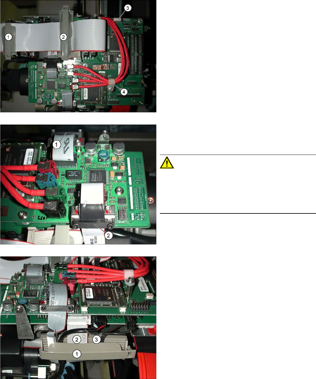
Cable clamps for flat ribbon cable
▪ The flat ribbon cable must be fixed with the clamps
(1) and (2). Use the "flat ribbon cable fastening
FCM3" 2 [03001829S01] for this.
▪ The narrower camera cable should be run under the
wide flat ribbon cable.
▪ Unused connector strips should be covered with a
plastic cap (3).
▪ The cable clamp (4) for the coax camera cables
needs to be fixed into place.
Fixture clamps
▪ The camera cables need to be fastened with fixture
clamps before the connector plugs.
CAUTION! Do not pinch the cables!
If the camera cable is pinched at the side and damaged,
this could lead to a short circuit (40V) and, for example,
could damage the DC/DC converter.
Always fix cables with a clamp in the middle (2). Do not
overtighten the screws of the fixture clamp.
▪ Check that the clamps are fixed properly at points (1)
and (2).
Securing the connector strip with a cable clamp
▪ To ensure reliable connections, use a cable clamp
(1).
▪ Inside the cable clamp, the cables should be run next
to one another, see also items (2), (3).
Service Work
4.5.21 Checking the Cable Routing C&P12 Placement Head
Service Manual SIPLACE D4/D4i 183
4.5.21.2
4.5.21.2 X Gantry Cable Routing
X Gantry Cable Routing
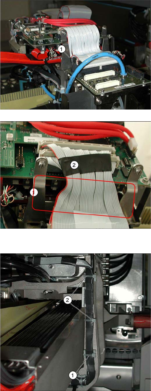
Avoid damage from old supporting plates
▪ Old supporting plates have a gap which is too narrow
for the flat ribbon cable. This could lead to the flat rib-
bon cable insulation being damaged.
▪ If the flat ribbon cable rubs against the supporting
plate, see item (1), either replace the supporting plate
or reduce the width of the flat ribbon cable according-
ly in the vicinity of the gap (2).
Reducing the width of the flat ribbon cable
▪ The width of the flat ribbon cable can be reduced
around the gap (1) by using a wide heat-shrinkable
sleeve or insulating tape (2).
▪ If the flat ribbon cable is damaged, replace it.
Use the "Cable /S-D placement head" [03047845-xx]
for this.
Avoid damage from the Y gantry.
Make sure that the X gantry cables do not touch the Y
gantry.
4 cables ties (1), (2) protect the cables from damage
caused by the Y gantry.
Always use small cable ties, which do not rub against the
gantry.
Service Work
C&P12 Placement Head 4.5.22 Press Fit Connections with Fixture Clips on the Vision Board (D Series)
184 Service Manual SIPLACE D4/D4i
4.5.21.3
4.5.21.3 Component Sensor Cable Routing
Component Sensor Cable Routing
4.5.21.4
4.5.21.4 Running the Valve Positioning Drive Cables
Running the Valve Positioning Drive Cables
4.5.22
4.5.22 Press Fit Connections with Fixture Clips on the Vision Board (D Series)
Press Fit Connections with Fixture Clips on the Vision Board (D Series)
Avoid loose cables.
The connection cables for the component sensor must be
fixed with a cable tie near to the press-fit connection, as
shown at (1).
The cable is run through the frame openings (2) and (4).
The cable is held by a cable tie at (3).
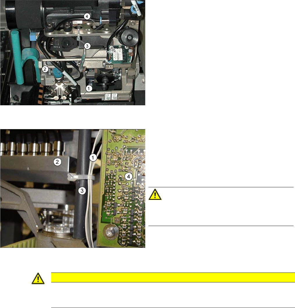
Avoid loose cables.
The diagram shows the board support to the side of the
placement head and the illumination board (4) on the
component camera.
The connection cables for the valve positioning drives (1)
of the reject and placement circuits need to be fixed at the
bolt of the board holder (3) with a cable tie (2).
CAUTION! Wrap insulating tape around bare
bolts
If the bolts are not already covered with a plastic hose, as
shown here, wrap insulating tape around the fixture point.
CAUTION
Do not damage the fixture clips!
To disconnect the component and PCB camera connections, you need to open the fixture clips
by applying pressure to the side of the connector.