SIPLACE D4-D4i 工程师手册_EN.pdf - 第185页
Service Work 4.5.23 Replacing the Raceway (Cir cular Arc Guide) C&P12 Placemen t Head Service Manual SIPLACE D4/D4i 185 4.5.23 4 . 5 . 2 3 R e p la c in g t h e R a c e w a y ( C ir c u la r A r c G u id e ) Replacin…
Service Work
C&P12 Placement Head 4.5.22 Press Fit Connections with Fixture Clips on the Vision Board (D Series)
184 Service Manual SIPLACE D4/D4i
4.5.21.3
4.5.21.3 Component Sensor Cable Routing
Component Sensor Cable Routing
4.5.21.4
4.5.21.4 Running the Valve Positioning Drive Cables
Running the Valve Positioning Drive Cables
4.5.22
4.5.22 Press Fit Connections with Fixture Clips on the Vision Board (D Series)
Press Fit Connections with Fixture Clips on the Vision Board (D Series)
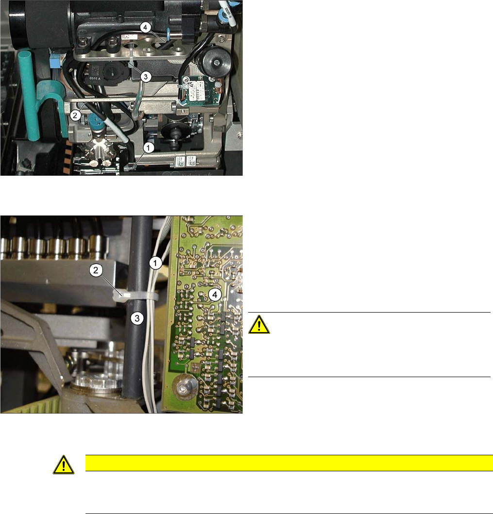
Avoid loose cables.
The connection cables for the component sensor must be
fixed with a cable tie near to the press-fit connection, as
shown at (1).
The cable is run through the frame openings (2) and (4).
The cable is held by a cable tie at (3).
Avoid loose cables.
The diagram shows the board support to the side of the
placement head and the illumination board (4) on the
component camera.
The connection cables for the valve positioning drives (1)
of the reject and placement circuits need to be fixed at the
bolt of the board holder (3) with a cable tie (2).
CAUTION! Wrap insulating tape around bare
bolts
If the bolts are not already covered with a plastic hose, as
shown here, wrap insulating tape around the fixture point.
CAUTION
Do not damage the fixture clips!
To disconnect the component and PCB camera connections, you need to open the fixture clips
by applying pressure to the side of the connector.
Service Work
4.5.23 Replacing the Raceway (Circular Arc Guide) C&P12 Placement Head
Service Manual SIPLACE D4/D4i 185
4.5.23
4.5.23 Replacing the Raceway (Circular Arc Guide)
Replacing the Raceway (Circular Arc Guide)
4.5.24
4.5.24 Replacing the Membrane (Vacuum Plate) on the Sleeve [03037984-xx]
Replacing the Membrane (Vacuum Plate) on the Sleeve [03037984-xx]
The sealing membrane on the sleeves ensures sufficient vacuum by sealing the tip of the nozzle (serves
as the air inlet) in the sleeve.
Tools and equipment
▪ Standard tool
▪ Spare part: membrane (vacuum plate) [03037984-xx]
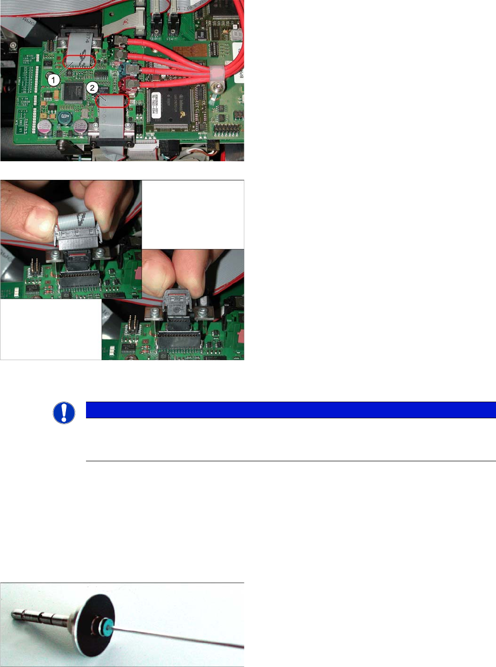
The adjacent diagram shows the press-fit connections for
the component camera (1) and the PCB camera (2) on
the Vision board of the SIPLACE D1/D2. Each of the two
positions has two connectors of different sizes with fixture
clips.
➢ To release the press-fit connections, press the con-
nector sides together at the top, with your thumb and
index finger.
► The fixture clips will open and the connector can be
pulled up and off.
⇨ The adjacent diagram shows the two press-fit con-
nections arranged one above the other, for the
Vision
signals
(small connector) and
illumination control
(large connector) after disconnection of the connec-
tors.
NOTICE
SIPLACE Service
This service task may only be performed by specially trained SIPLACE service technicians. The
procedure is described in a separate manual.
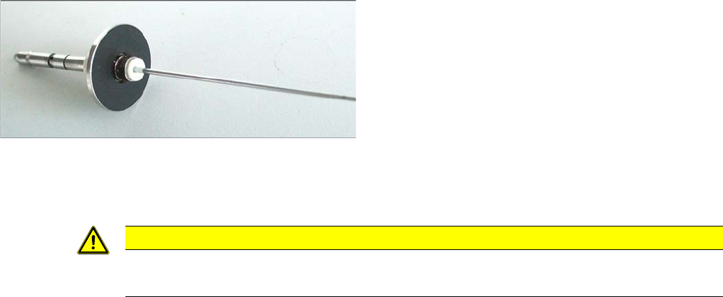
Blue membrane for the sleeve with ball fixing C&P6/12
(old version [00354244-xx])
Service Work
C&P12 Placement Head 4.5.25 Replacing the Vacuum Hoses on the C&P Head
186 Service Manual SIPLACE D4/D4i
Removal
► Loosen the old membrane with an Allen key (1.5 mm) and remove the membrane.
Installation
► Fit the new membrane onto the sleeve and tighten the membrane with an Allen key.
4.5.25
4.5.25 Replacing the Vacuum Hoses on the C&P Head
Replacing the Vacuum Hoses on the C&P Head
The length of the vacuum hoses and the way in which they are fitted has been improved to ensure that,
when the hoses are replaced - especially in SX, DX, X, D3 and HF machines - these hoses can be run
in a manner which will not interrupt the vacuum supply.
Tools and equipment
▪ Standard tool
▪ Spare part: vacuum hoses and guidance [03064147-xx]
Contents:
– Hose for placement circuit query (new length: 180 mm, old length: 190 mm) [03002187-02]
– Hose for holding circuit query (new length: 225 mm, old length: 200 mm) [03002188-02]
– Hose for placement circuit / 3x6x145 (new length: 145 mm, old length: 125 mm) [03010444-02]
– Hose for hold circuit / 4x7x140 [03010445S01]
– Hose guide [03048807-01]
– Cylinder screw M3x6 DIN912-A2 [03045028-01]
White membrane for the sleeve with ball fixing C&P6/12,
made of an alternative material
(new version [03037984-xx])
CAUTION
Do not use a ball Allen key!
► Make sure that you do not use a ball Allen key.