SIPLACE D4-D4i 工程师手册_EN.pdf - 第189页
Measuring Equipment and Tools SIPLACE Axis Tester (SAT) [03002801-01] Service Manual SIPLACE D4/D4i 189 5 5 M e a s u r in g E q u ip m e n t a n d T o o ls Measuring Equipment and Tools 5.1 5 . 1 S I P L A C E A x is T …
Service Work
Pneumatic Unit 4.6.1 Safety Instructions for Replacing Parts
188 Service Manual SIPLACE D4/D4i
4.6
4.6 Pneumatic Unit
Pneumatic Unit
4.6.1
4.6.1 Safety Instructions for Replacing Parts
Safety Instructions for Replacing Parts
4.6.2
4.6.2 Preparing for Part Replacement
Preparing for Part Replacement
► End all placement operations on the placement system.
► Shut down the Windows NT operating system correctly, otherwise problems may occur when restart-
ing or data may be lost.
► Switch the placement system off at the main switch.
► Disconnect the machine from the power supply.
► Secure the machine to prevent it being switched on again and put up warnings signs to indicate that
service work is in progress.
WARNING
NEVER disconnect compressed air lines while they are still pressurized. Risk of injury!
DANGER
The machine is supplied with 3 x 400 V~ (or 3 x 204 V~ / 3 x 230 V~ / 3 x 380 V~ / 3 x 415 V~)
± 5 %, 50/60 Hz mains voltage.
Consequently, parts of the system carry potentially lethal voltages, even when it is switched off
at the main switch.
Incorrect handling of the machine can therefore result in death, severe injury or considerable
damage to equipment.
Measurements and repairs must always be carried out by appropriately qualified personnel.
Always follow the safety instructions in this manual.
Always follow the applicable accident prevention and VDE regulations (particularly DIN EN 60
204 part 1) or the regulations specific to your country.
Before starting any repairs, switch off at the main switch and disconnect the machine from the
mains power supply.
Secure the system to prevent it being switched on again. If these instructions are not followed,
you may be able to touch live parts, which could result in death or severe injury.
Measuring Equipment and Tools
SIPLACE Axis Tester (SAT) [03002801-01]
Service Manual SIPLACE D4/D4i 189
5
5 Measuring Equipment and Tools
Measuring Equipment and Tools
5.1
5.1 SIPLACE Axis Tester (SAT) [03002801-01]
SIPLACE Axis Tester (SAT) [03002801-01]
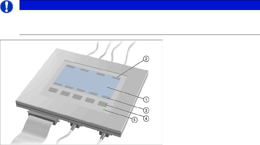
Axis tester - view from above
1. LCD display with 240 x 128 pixels, black-and-white display, with background illumination
The LCD display shows the menus and the recorded trigger, track and position signals. All relevant
parameters, such as
– Time basis,
– Time measurement values,
– Signal levels and
– Cursor positions with the corresponding time deviation values
are shown as alphanumerical data in the diagram of the measurement curves.
2. Dynamic function display of BNC socket arrangement on the LCD display
3. Dynamic function display of foil button arrangement on the LCD display
4. Five foil buttons for menu control
5. Green LED for displaying operation
NOTICE
A363, A364
The axis tester is designed for all machines with A363. This function is limited for machines
with A364.
Measuring Equipment and Tools
SIPLACE Axis Tester (SAT) [03002801-01]
190 Service Manual SIPLACE D4/D4i
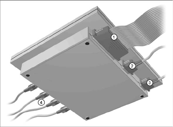
Axis tester - view from below
1. Connection for flat ribbon cable:
– At the axis tester end:
– 37-pin sub-d connector
– At the axis control end:
– 37-pin sub-d connector for the S-20/23/25/F4/F5 and HS-50 machines with the axis control
A361 or A362
– 25-pin sub-d connector for the S-15/F3, G machines and wafflepack changer with the axis con-
trol A360
An adapter is fitted to the flat ribbon cable to connect the 25-pin axis control. The operating volt-
ages of +5 V- ±5 % and ±15 V- ±5 % are fed via the 37 pin flat ribbon cable from the axis control
unit to the axis tester.
2. 9 pin Sub-D connector for CAN Bus cable e.g. for connection of CAN Bus controlled boards in the
machine – currently not used (transmission rate 128 kBaud to 1 MBaud, impedance 120 Ohm)
3. 9 pin Sub-D connector for the serial interface cable (V24) needed for software downloads, e.g. for
connection of an external PC (max. transmission rate up to 188 kBaud)
4. Four BNC sockets, connection impedance 50 Ohm. Socket assignment can be programmed. The
following signals can be assigned:
– Track signal A or B TTL level, max. 5 V
– Zero pulse TTL level tmin = 1 µsec
– End position signal TTL level tmin > 10 msec
– Trigger TTL level tmin > 10 msec
– Count error TTL level, trigger signal from count error sensor of oscilloscope
– Vtarget ±10 V, analog signal, Ri = 10 kOhm
– Force ±10 V analog signal, Ri = 10 kOhm
– VREG (resulting current) ±10 V analog signal, Ri = 10 kOhm
– Position deviation ±10 V analog signal; signal is generated internally, in the axis tester.