SIPLACE D4-D4i 工程师手册_EN.pdf - 第190页
Measuring Equipmen t and Tools SIPLACE Axis Tester (SAT) [03002801-01] 190 Service Manual SIPLACE D4/D4i Axis tester - view from below 1. Connection for flat r ibbon cable: – At the axis tester end: – 37-pin sub-d connec…
Measuring Equipment and Tools
SIPLACE Axis Tester (SAT) [03002801-01]
Service Manual SIPLACE D4/D4i 189
5
5 Measuring Equipment and Tools
Measuring Equipment and Tools
5.1
5.1 SIPLACE Axis Tester (SAT) [03002801-01]
SIPLACE Axis Tester (SAT) [03002801-01]
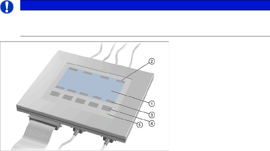
Axis tester - view from above
1. LCD display with 240 x 128 pixels, black-and-white display, with background illumination
The LCD display shows the menus and the recorded trigger, track and position signals. All relevant
parameters, such as
– Time basis,
– Time measurement values,
– Signal levels and
– Cursor positions with the corresponding time deviation values
are shown as alphanumerical data in the diagram of the measurement curves.
2. Dynamic function display of BNC socket arrangement on the LCD display
3. Dynamic function display of foil button arrangement on the LCD display
4. Five foil buttons for menu control
5. Green LED for displaying operation
NOTICE
A363, A364
The axis tester is designed for all machines with A363. This function is limited for machines
with A364.
Measuring Equipment and Tools
SIPLACE Axis Tester (SAT) [03002801-01]
190 Service Manual SIPLACE D4/D4i
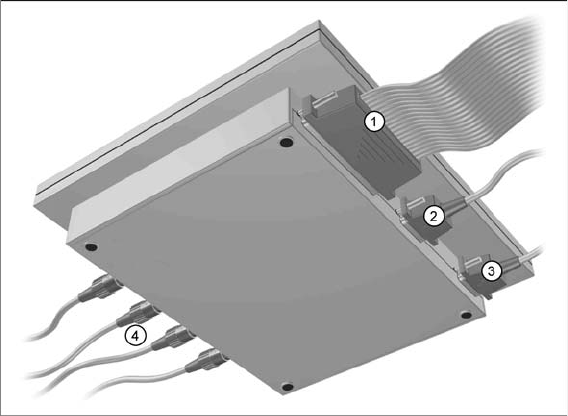
Axis tester - view from below
1. Connection for flat ribbon cable:
– At the axis tester end:
– 37-pin sub-d connector
– At the axis control end:
– 37-pin sub-d connector for the S-20/23/25/F4/F5 and HS-50 machines with the axis control
A361 or A362
– 25-pin sub-d connector for the S-15/F3, G machines and wafflepack changer with the axis con-
trol A360
An adapter is fitted to the flat ribbon cable to connect the 25-pin axis control. The operating volt-
ages of +5 V- ±5 % and ±15 V- ±5 % are fed via the 37 pin flat ribbon cable from the axis control
unit to the axis tester.
2. 9 pin Sub-D connector for CAN Bus cable e.g. for connection of CAN Bus controlled boards in the
machine – currently not used (transmission rate 128 kBaud to 1 MBaud, impedance 120 Ohm)
3. 9 pin Sub-D connector for the serial interface cable (V24) needed for software downloads, e.g. for
connection of an external PC (max. transmission rate up to 188 kBaud)
4. Four BNC sockets, connection impedance 50 Ohm. Socket assignment can be programmed. The
following signals can be assigned:
– Track signal A or B TTL level, max. 5 V
– Zero pulse TTL level tmin = 1 µsec
– End position signal TTL level tmin > 10 msec
– Trigger TTL level tmin > 10 msec
– Count error TTL level, trigger signal from count error sensor of oscilloscope
– Vtarget ±10 V, analog signal, Ri = 10 kOhm
– Force ±10 V analog signal, Ri = 10 kOhm
– VREG (resulting current) ±10 V analog signal, Ri = 10 kOhm
– Position deviation ±10 V analog signal; signal is generated internally, in the axis tester.
Measuring Equipment and Tools
5.1.1 Scope of Delivery SIPLACE Diagnosis Adapter A364 [03051220-01]
Service Manual SIPLACE D4/D4i 191
5.1.1
5.1.1 Scope of Delivery
Scope of Delivery
The SIPLACE axis tester package [03002801-01] contains the following components:
▪ SIPLACE axis tester [03000761-01]
▪ Test cable A361 ... A363 (length 150 cm) with 37 pin connector and 37 pin socket for connection of
axis control units from S2x, F4/F5 and HS machines [03002803-01]
▪ CAN Bus cable [00349679-03]
▪ RS232-C cable [03002804-01]
▪ Manual for axis tester [00193370-01]
5.2
5.2 SIPLACE Diagnosis Adapter A364 [03051220-01]
SIPLACE Diagnosis Adapter A364 [03051220-01]
Application:
This adapter card is used to check the A364 axis card dynamics.
The A364 axis card is equipped with two processors (module 1 and module 2) i.e. one processor controls
two axes.
NOTICE
A364, CAN test box
This adapter is designed for all machines with A364 and as an adapter for the CAN test box
with force measuring tool.
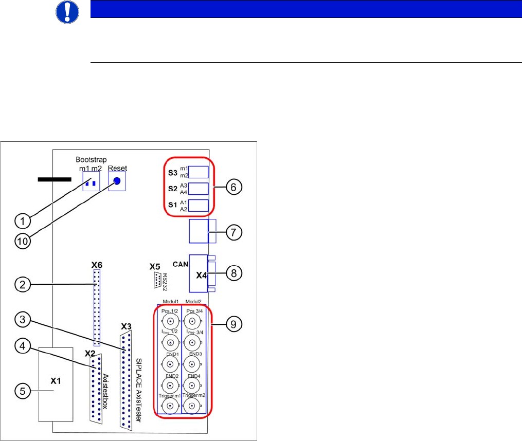
Adapter card for A364
Module 1: axis 1/2
Module 2: axis 3/4
1. Bootstrap mode: m1 = module1 / m2 = module2
2. Diagnosis – connector X6
3. Connection X3 SIPLACE AxisTester
4. Connection X2 Axis test box
5. Connection X1 to A364
6. Switches:
7. Diagnosis – 7 segment display
8. CAN bus connector (Sub-D)
9. BNC sockets:
10. Reset both processors