SIPLACE D4-D4i 工程师手册_EN.pdf - 第196页
Measuring Equipmen t and Tools Calibration Tool [03010565-xx] 5.1.1 Scope of Delivery 196 Service Manual SIPLACE D4/D4i 5.11 5 . 1 1 C a lib r a t io n T o o l [ 0 3 0 1 0 5 6 5 - x x ] Calibration Tool [03010565-xx] 5.1…
Measuring Equipment and Tools
5.1.1 Scope of Delivery Z End Stopper Star Gauge for C&P6/12 03019865-xx
Service Manual SIPLACE D4/D4i 195
5.9
5.9 Z End Stopper Star Gauge for C&P6/12 03019865-xx
Z End Stopper Star Gauge for C&P6/12 03019865-xx
5.10
5.10 Adjustment Aid for C&P DLM 00327005-xx
Adjustment Aid for C&P DLM 00327005-xx
Use:
The gauge is used to set the end stop position of the C&P
head Z axis.
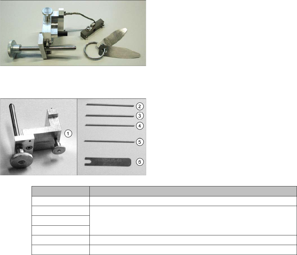
Complete set [00327005-xx]
1. Gauge for star [00326164-xx]
2. Test probe 1.4 mm [00326160-xx]
3. Test probe 1.5 mm [00326161-xx]
4. Test probe 1.6 mm [00326162-xx]
5. Test probe 1.0 mm [00376656-xx]
6. Distance gauge [00325445-xx]
Measurement tools Application type
Gauge for star Setting the zero point correction for the star
Test probe 1.4 mm Setting the distance between the DP station incremental encoder and the glass
for the sleeve
Test probe 1.5 mm
Test probe 1.6 mm
Test probe 1.0 mm Setting the distance from the Z axis light barrier down to the sleeve shaft
Distance gauge Setting the distance of the valve plunger to the star
Measuring Equipment and Tools
Calibration Tool [03010565-xx] 5.1.1 Scope of Delivery
196 Service Manual SIPLACE D4/D4i
5.11
5.11 Calibration Tool [03010565-xx]
Calibration Tool [03010565-xx]
5.12
5.12 Calibration Nozzle for TwinHead [03008862-xx]
Calibration Nozzle for TwinHead [03008862-xx]
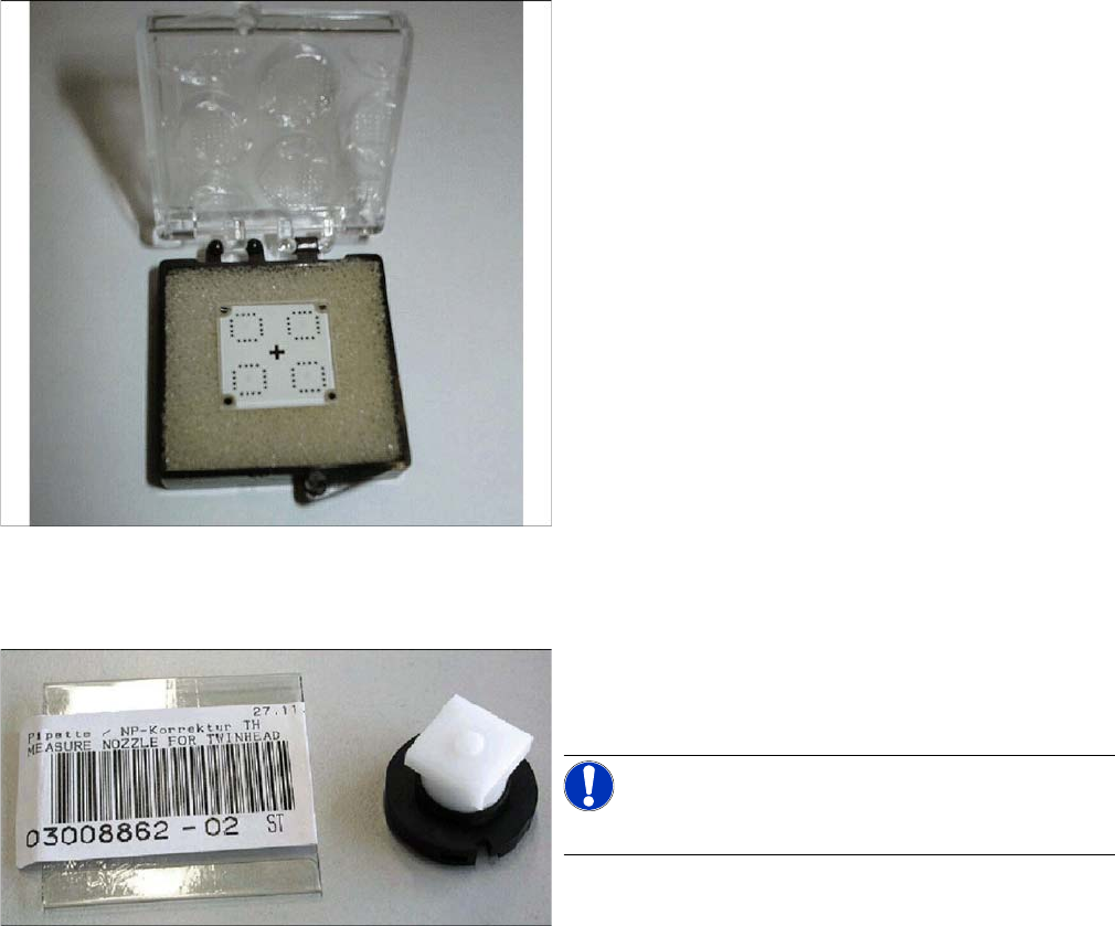
Use:
The calibration tool [03010565-xx] is used for calibration
of the DLM, CPP, P&P heads, TwinHead and PCB cam-
era.
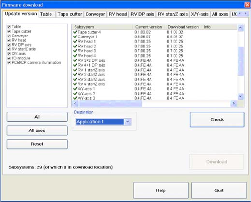
Use:
The calibration nozzle is used to calibrate the D axis of
the TwinHead or P&P head.
NOTICE!
This nozzle is no longer needed from SW705.03.
Settings
6.1.1 Checking the Firmware Function Electrical System
Service Manual SIPLACE D4/D4i 197
6
6 Settings
Settings
The electrical assemblies are in part set via jumpers or DIP switches. The following tables provide a brief
overview of the electrical settings. For details, please consult the setting instructions.
6.1
6.1 Electrical System
Electrical System
6.1.1
6.1.1 Checking the Firmware Function
Checking the Firmware Function
6.1.2
6.1.2 Firmware Download Note
Firmware Download Note
From the following station software versions, the firmware download can be performed to all CAN bus
nodes, via the standard SITEST interface.
▪ 505.04 SP2
▪ 603.01 SP1
▪ 604.01 SP1
6.2
6.2 Gantry
Gantry
6.2.1
6.2.1 Travel Ranges and Speed Monitoring (A364)
Travel Ranges and Speed Monitoring (A364)
The travel range of the X and Y axes will be determined automatically with the SITEST program.
This means that, during travel range calibration, the axis concerned moves as far as possible towards
the minimum or maximum position, until the set axis card target value is no longer reached. It is then
assumed that the hardware limit switch (buffer) has been reached. In a time window of approx. 10 ms,
the greatest actual value achieved is taken to calculate the travel range.
To guarantee an appropriate safety gap before the hardware end switch is touched, a certain distance
is deducted from the set travel range. This enables the axis to brake in time, even when errors occur.
► Select a Target (BIOS/application 1/application 2)
and click on the Check.