SIPLACE D4-D4i 工程师手册_EN.pdf - 第200页
Settings Gantry 6.2.3 Description of the PCB boards on the Gantry 200 Service Manual SIPLACE D4/D4i 6.2.2.5 6 . 2 . 2 . 5 A n t ic r a s h F u n c t io n - P r o c e d u r e Anticrash Function - Procedure Example of the …

Settings
6.2.2 Anticrash Function for the A364 Axis Card Gantry
Service Manual SIPLACE D4/D4i 199
6.2.2
6.2.2 Anticrash Function for the A364 Axis Card
Anticrash Function for the A364 Axis Card
6.2.2.1
6.2.2.1 Anticrash Function for the A364
Anticrash Function for the A364
▪ The anticrash function is no longer provided by the anticrash board but instead by the A364 software
(application 1). This means that the proximity switches used to monitor the travel range and the sen-
sor for monitoring the gantry spacing are no longer required.
▪ Tasks:
– Monitoring the X and Y axis travel ranges
Evaluation of the actual position of the respective axis in the direction of the bumper, based on
the speed.
– Monitoring the distance of both Y axes in a placement area
Evaluation of the actual position of the own gantry and the partner gantry plus the respective
speed at gantry crash monitoring.
– Axis count error
Monitoring incoming count pulses (edge control) over time.
6.2.2.2
6.2.2.2 Anticrash Monitoring for the A364
Anticrash Monitoring for the A364
The anticrash function is activated after the X/Y axes have been referenced. When the gantry axes are
referenced for the first time, anticrash monitoring will not be active, which is not so important, due to the
low reference speed.
After this, the bit is set for the anticrash monitoring function and the actual position for the relevant part-
ner gantry is continuously communicated via the SPI Bus.
The following information is exchanged between the Y axes:
▪ Actual position of the own gantry
▪ Gantry speed
▪ Status information (reference state, anticrash monitoring state ).
Anticrash Monitoring Settings for the A364
6.2.2.3
6.2.2.3 Error "Gantry Crash"
Error "Gantry Crash"
A “gantry crash” error is established by calculating the position difference and speed difference for both
axes. A gantry crash error is signaled via the axis card and the CAN Bus. The servo is released for both
axes and both need to be referenced again.
6.2.2.4
6.2.2.4 Count Error:
Count Error:
If the axis board detects a "fatal count error", the axis concerned will be released and the anticrash func-
tion disabled. The other axis is informed of this in the status information and will also disable the ant-
icrash function. The released axis now needs to be referenced again.
after which the anticrash function will be re-enabled for both axes.
NOTICE
No settings
The anti-crash monitoring function is controlled by a rapid software regulator. This means that
there are no longer any settings required for the anti-crash monitoring.
Settings
Gantry 6.2.3 Description of the PCB boards on the Gantry
200 Service Manual SIPLACE D4/D4i
6.2.2.5
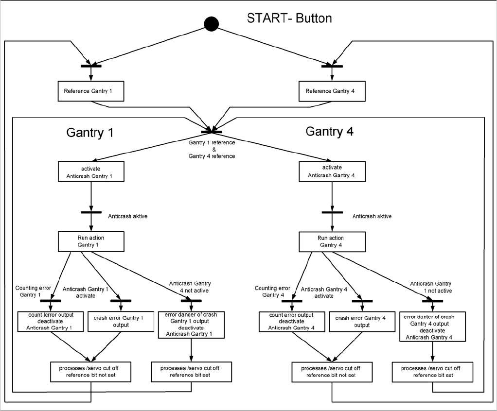
6.2.2.5 Anticrash Function - Procedure
Anticrash Function - Procedure
Example of the sequence for the anticrash function in placement area 1
6.2.3
6.2.3 Description of the PCB boards on the Gantry
Description of the PCB boards on the Gantry
The boards on the gantry described below are basically identical and do not depend on the head con-
figuration of D1, D2 and D4 machines (the D3 has a different board here). The CAN bus terminating re-
sistor is fixed onto the gantry head distributor.
Settings
6.2.3 Description of the PCB boards on the Gantry Gantry
Service Manual SIPLACE D4/D4i 201
6.2.3.1
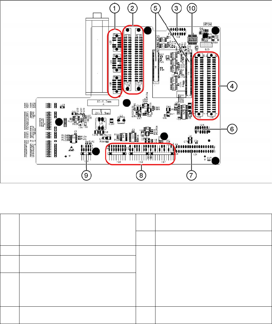
6.2.3.1 Gantry Head Distributor
Gantry Head Distributor
Gantry head distributor (from above)
Legend
1 X20 stepping motor for reject position
X19 stepping motor for pickup/place
X18 stepping motor for swiveling in the DP
axis
6 X24 Test connector for „digital track signals
for X-axis“
7 X29 connector for Vision board
2 X13/X14 flat ribbon cable to C&P head 8 X10 Connector vacuum measurement
board
X12 DP axis motor
X16 Reference proximity switch (nor used)
X17 X-axis end position proximity switch
(not used)
X22 Temperature feeler
X21 Free (not used)
3 X11 test connector for CAN Bus, SPI Bus,
RS232
4 X30/X31 flat ribbon cable to P&P head for
D1/D1i (D4/D4i not in use)
5 X5/X6 connector for 16 bit processor
(TQM)
9 X26 connector for CO sensor