SIPLACE D4-D4i 工程师手册_EN.pdf - 第210页
Settings C&P12 6.3.3 Overview of Settings on the C&P6/12 210 Service Manual SIPLACE D4/D4i 6.3.3 6 . 3 . 3 O v e r v ie w o f S e t t in g s o n t h e C & P 6 / 1 2 Overview of Settings on the C&P6/12 Des…
Settings
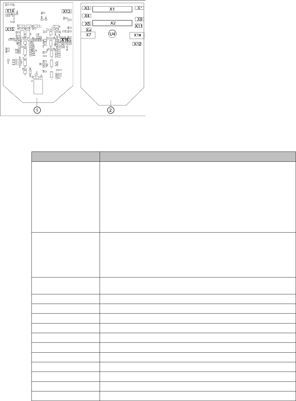
6.3.2 Boards at C&P12 C&P12
Service Manual SIPLACE D4/D4i 209
The following supply voltages and signals are routed by the intermediate distributor to the individual
placement head modules or to the head board:
Position of the sockets
Legend
1. Front of the intermediate distributor
2. Back of the intermediate distributor
U4 = pressure sensor
Two 40-pin ribbon cables run from plug X1 and X2 on the
intermediate distributor to socket X14 / X13 on the head
board.
Connectors Description
X1, 40-pole Connected to plug X14 on the head board
▪ Voltage supply, tacho and track signals for the Z axis drive
▪ Signal from light barrier "Z axis in top position"
▪ Signal from light barrier "Z axis in bottom position" (sensor stop signal)
▪ Control signal for the air blast valve
▪ Supply voltage +5 VDC, ±15 VDC
▪ Reference point signal for the DP axis
▪ Track signals for the DP axis
X2, 40-pole Connected to plug X13 of the gantry head distributor
▪ Voltage supply and track signals for the star axis drive
▪ Reference point for the star axis
▪ Analog air blast pressure value
▪ Supply voltages +5 VDC, ±15 VDC, +24 VDC
X3, 10-pole Connection for the Z motor and Z tacho signal (tacho signal is not used on
the HF machine)
X4, 10-pole Connection for the Z axis track signals
X5, 10-pole Connection for the star motor
X6, 6-pole Connection for the air blast valve
X7, 10-pole Connection for the DP axis track signals
X10, 10-pole Connection for the "Z axis up" signal
X11, 8-pole Connection for the light barrier "Z axis down" signal (sensor stop signal)
X12, 10-pole Connection for the star axis track signals
X13, 10-pole Test connection for the Z axis track signals
X14, 10-pole not used
X15, 10-pole Test connection for the star axis track signals
X16, 10-pole Test connection for the DP axis track signals

Settings
C&P12 6.3.3 Overview of Settings on the C&P6/12
210 Service Manual SIPLACE D4/D4i
6.3.3
6.3.3 Overview of Settings on the C&P6/12
Overview of Settings on the C&P6/12
Description Tools and equipment Values
Mount the star onto the motor
shaft of the star motor
Adjust with the power pack and
star zero point gauge
Check the magnetic neutral posi-
tion in SITEST
(max. deviation 95 digits)
Determine zero point correction
for the star.
Gauge for zero point correction /
SITEST
Enter result of zero point correc-
tion with SITEST
--> enter positions.
Switch position on star motor
(resolution of track signals 10 -
25)
none HF/X/D machines at"6.3.4 Set-
ting the Resolution on the Star
Axis" [ ➙ 211]25
DP axis incremental encoder ad-
justment to the glass scale (seg-
ment)
Test probe 1.4 - 1.6 mm Distance 1.5 mm.
Adjustment mechanical position
of valve positioning drives
Distance gauge 0.2 mm or ad-
justment plunger
0.2 mm distance plunger to the
valve frame
Light barrier Z axis down Test probe 1.0 mm Distance 1.0 mm.
Clamping device on Z belt --- Tension jack must lie on the belt
teeth at the top and bottom.
Belt tension of the Z axis Belt tension measurement de-
vice
Belt tension 280 +/- 5 Hz
Z axis top stop Gauge for Z axis end stopper -
star gauge [03019865-xx]
Correct position is necessary to
determine the zero point correc-
tion.
Air blast tubes on the star Check with your eyes Check the distance between in-
cremental encoder and air blast
tubes.
Adjustment of air blast supply Feeler gauge Air blast tubes should be approx.
0.7 mm over the frame of the cir-
cular arc guide
Adjustment of air blast placement Compressed air testing device 150 mbar on open 9x4 nozzle
Air blast setting on reject circuit Compressed air testing device250 mbar
Belt tension setting for drive belt
replacement
DP belt adjustment aid Achieved with spring tension of
tool
Settings
6.3.4 Setting the Resolution on the Star Axis C&P12
Service Manual SIPLACE D4/D4i 211
6.3.4
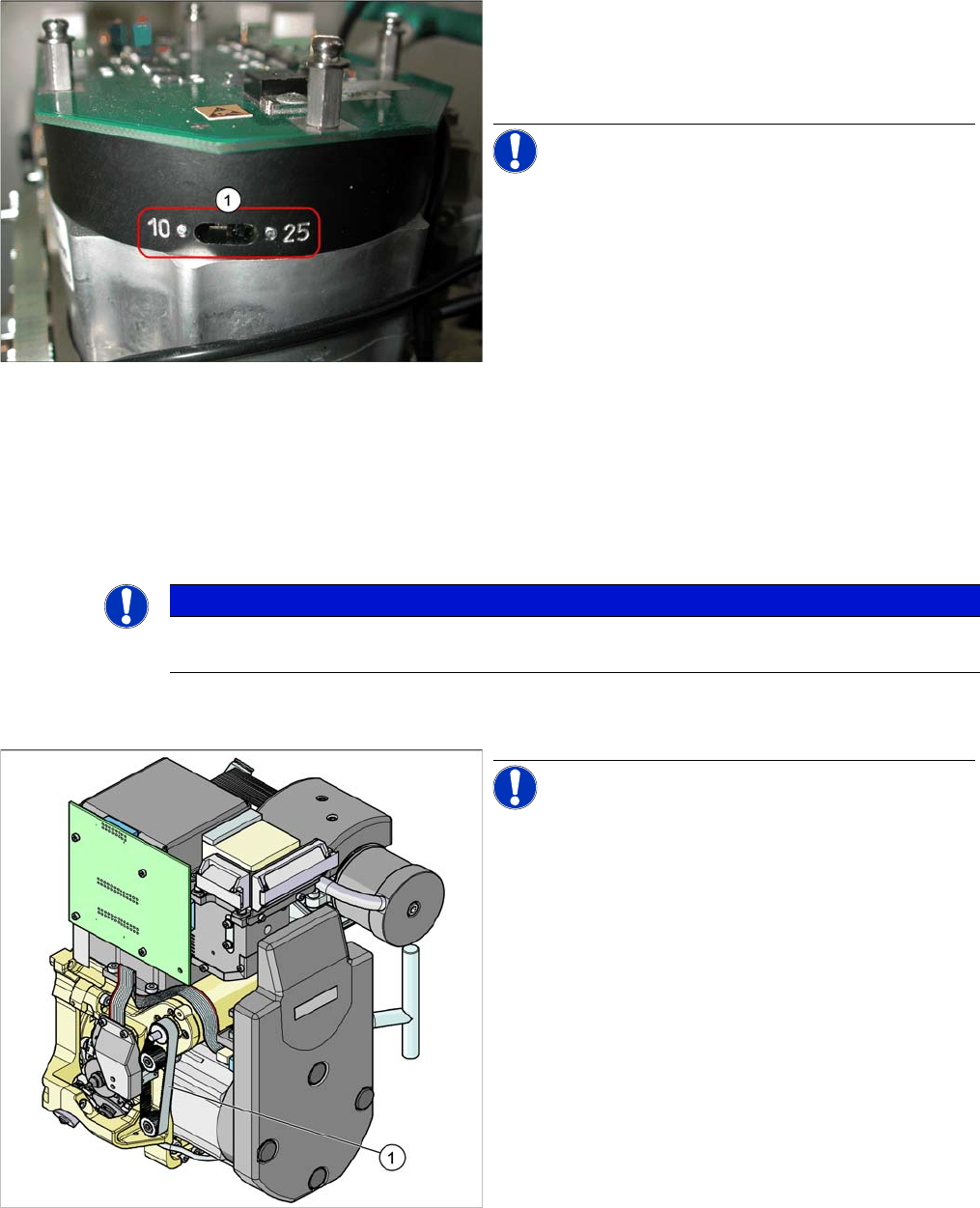
6.3.4 Setting the Resolution on the Star Axis
Setting the Resolution on the Star Axis
6.3.5
6.3.5 Setting the Digital Rotary Encoder for the DP Axis
Setting the Digital Rotary Encoder for the DP Axis
▪ Remove sleeve 1 and insert the Star zero point gauge, in order to mechanically fix the Star.
▪ Now, remove sleeve 4 or the sleeve 2 for the 6 segment C&P head as well and align the transducer.
▪ With the help of a parallel pin, set the rotary transducer of the DP - axis to 1.5 mm, parallel to the
glass pane of the segments.
6.3.6
6.3.6 Setting the Z axis Belt Tension
Setting the Z axis Belt Tension
Setting the Resolution on the Star Axis
Legend
1. The switch for the star axis resolution is directly be-
neath the C&P head on the star motor.
► Check the setting of this switch (1).
NOTICE! Only set the switch if the machine
power is off.
▪ HS-60, HS-50, S-27 HM, S-25 HM, S23 HM: Switch
position 10
▪ D, HF/HF3 and X machines: Switch position 25
NOTICE
Make sure that a 1.4 mm test probe can be easily passed through and that a probe with 1.6 mm
can not be passed through.
Measurement point for belt tension
NOTICE! The measurement point on the meas-
urement head should be in the middle, between two de-
flection pulleys.The measurement head should be kept at
a distance of maximum 2 - 3 mm from the toothed belt.
Legend
1. Measurement point for the belt tension
► Hold the measuring head of the belt tension measur-
ing device in front of the toothed belt (1) .
► Strike the toothed belt, to reach a stimulation of vibra-
tion of the open ended toothed belt.
► If the belt tension frequency does not match the value
280 Hz ±10 Hz, tension or relax the belt via the drive
motor fastening.
► Repeat these instructions until the belt tension is cor-
rect.