SIPLACE D4-D4i 工程师手册_EN.pdf - 第212页
Settings C&P12 6.3.7 Adjusting the Stop for the Z Axis 212 Service Manual SIPLACE D4/D4i 6.3.7 6 . 3 . 7 A d ju s t in g t h e S t o p f o r t h e Z A x is Adjusting the Stop for the Z Axis 6.3.7.1 6 . 3 . 7 . 1 T o …
Settings
6.3.4 Setting the Resolution on the Star Axis C&P12
Service Manual SIPLACE D4/D4i 211
6.3.4
6.3.4 Setting the Resolution on the Star Axis
Setting the Resolution on the Star Axis
6.3.5
6.3.5 Setting the Digital Rotary Encoder for the DP Axis
Setting the Digital Rotary Encoder for the DP Axis
▪ Remove sleeve 1 and insert the Star zero point gauge, in order to mechanically fix the Star.
▪ Now, remove sleeve 4 or the sleeve 2 for the 6 segment C&P head as well and align the transducer.
▪ With the help of a parallel pin, set the rotary transducer of the DP - axis to 1.5 mm, parallel to the
glass pane of the segments.
6.3.6
6.3.6 Setting the Z axis Belt Tension
Setting the Z axis Belt Tension
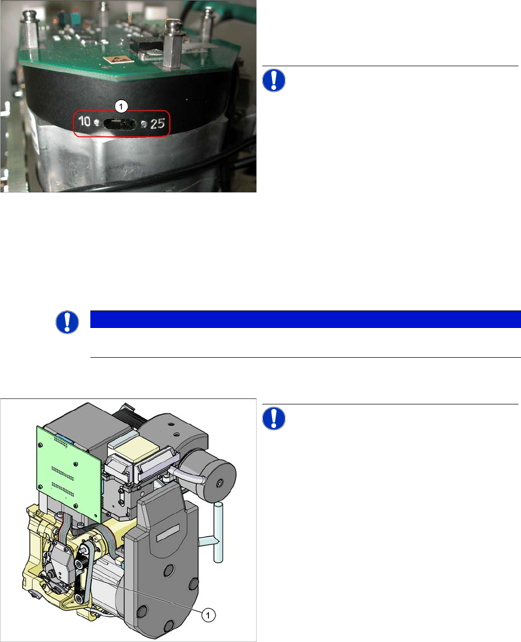
Setting the Resolution on the Star Axis
Legend
1. The switch for the star axis resolution is directly be-
neath the C&P head on the star motor.
► Check the setting of this switch (1).
NOTICE! Only set the switch if the machine
power is off.
▪ HS-60, HS-50, S-27 HM, S-25 HM, S23 HM: Switch
position 10
▪ D, HF/HF3 and X machines: Switch position 25
NOTICE
Make sure that a 1.4 mm test probe can be easily passed through and that a probe with 1.6 mm
can not be passed through.
Measurement point for belt tension
NOTICE! The measurement point on the meas-
urement head should be in the middle, between two de-
flection pulleys.The measurement head should be kept at
a distance of maximum 2 - 3 mm from the toothed belt.
Legend
1. Measurement point for the belt tension
► Hold the measuring head of the belt tension measur-
ing device in front of the toothed belt (1) .
► Strike the toothed belt, to reach a stimulation of vibra-
tion of the open ended toothed belt.
► If the belt tension frequency does not match the value
280 Hz ±10 Hz, tension or relax the belt via the drive
motor fastening.
► Repeat these instructions until the belt tension is cor-
rect.
Settings
C&P12 6.3.7 Adjusting the Stop for the Z Axis
212 Service Manual SIPLACE D4/D4i
6.3.7
6.3.7 Adjusting the Stop for the Z Axis
Adjusting the Stop for the Z Axis
6.3.7.1
6.3.7.1 Tools and Equipment
Tools and Equipment
6.3.7.2
6.3.7.2 General
General
From software version 601.01 onwards, during the reference run, the Z axis moves into the star position
with +/-6250/6750 digits downwards or up into the crank, to determine the Z axis zero point correction
factor. The prerequisite for this is the correct setting of the upper end position stop of the Z axis. This
ensures that the Z axis is in the center of the raceway and that the Z axis zero point can be correctly
determined.
Preconditions:
Before you begin adjustment work, check the belt tension and the correct installation of the belt lock at
the Z axis.
6.3.7.3
6.3.7.3 Settings
Settings
► Switch off the machine. This setting can be performed directly at the machine.
► The star gauge for setting the Z end stopper is mounted on the C&P head in exactly the same way
as the zero point gauge for the star.
► Remove segment 1 and rotate the star until the gauge pin fits into the segment guidance.
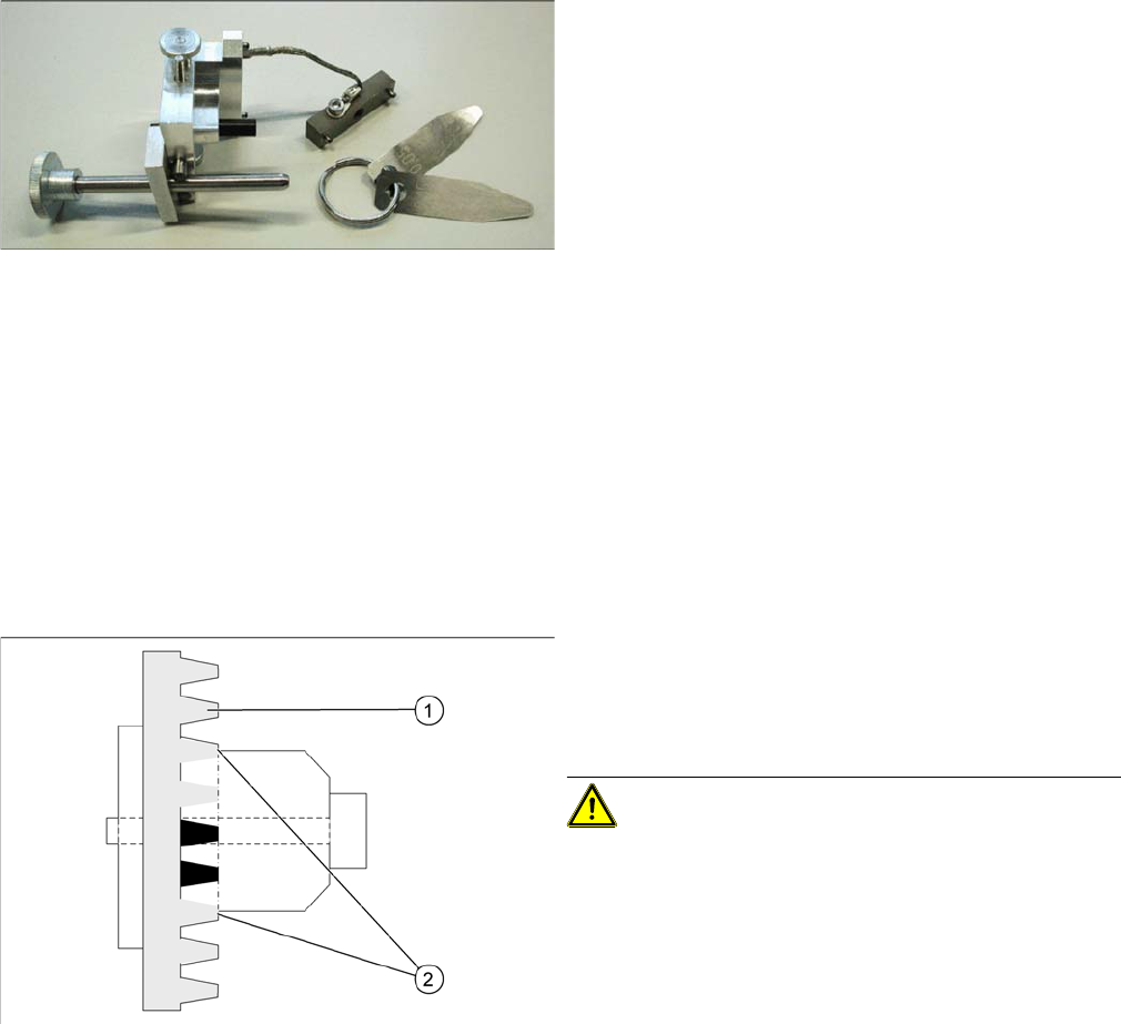
Gauge for Z end stopper
▪ Set of DIN 911 Allen keys
▪ Gauge for Z axis end stopper - star gauge
[03019865-xx]
Clamping device Z axis
Legend
1. Belt tension Z Axis
2. Tension jack is positioned on the teeth at the top and
bottom
CAUTION! Make sure that both ends of the ten-
sion jack lie on the teeth of the toothed belt.
Settings
6.3.7 Adjusting the Stop for the Z Axis C&P12
Service Manual SIPLACE D4/D4i 213
► For better access to the Z axis end stopper, unscrew the cable clamp at one side and turn it to the
side. Then carefully push the flat ribbon cable to the side.
► Check whether the 5/100 mm feeler gauge passes easily (without resistance) between the Z axis
end stopper and the tension jack (see diagram above).
► If this is not the case, you will need to adjust the Z axis end stopper setting!
► Loosen the Z axis end stopper screw.
► Clamp a 15/100 mm feeler gauge between the Z end stopper and the clamp. Gently press the Z axis
end stopper downwards with the screwdriver and screw tight.
► It should now be more difficult to extract the 15/100 mm feeler gauge.
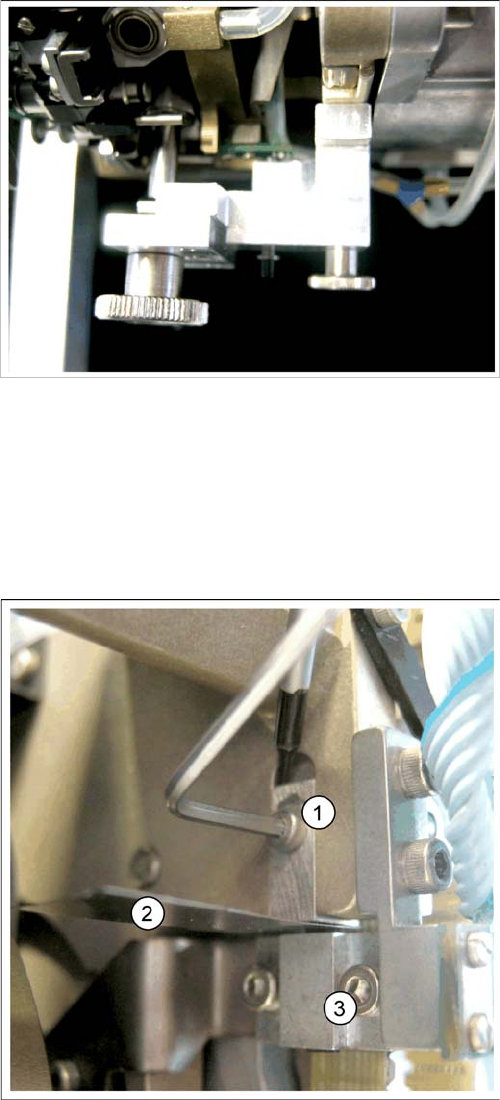
Z end stopper star gauge mounted
The star gauge ensures that the star is in the correct po-
sition and that the Z axis is pressed upwards.
Z end stopper check and adjust
Legend
1. Z end stopper
2. Feeler gauge
3. Clamping device