SIPLACE D4-D4i 工程师手册_EN.pdf - 第217页
Settings 6.3.11 Adjustment of air pressure values C&P12 Service Manual SIPLACE D4/D4i 217 6.3.11 6 . 3 . 1 1 A d ju s t m e n t o f a ir p r e s s u r e v a lu e s Adjustment of air pressure values 6.3.11.1 6 . 3 . 1…
Settings
C&P12 6.3.10 Setting the Mechanical Position of the Valve Positioning Drives
216 Service Manual SIPLACE D4/D4i
6.3.10
6.3.10 Setting the Mechanical Position of the Valve Positioning Drives
Setting the Mechanical Position of the Valve Positioning Drives
▪ Set the motor position of the valve positioning drives "pickup/placement" and "reject" as shown in the
following diagram.
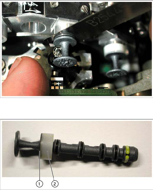
▪ If the new valve plungers are used (s. diag. below) proceed as follows: Take out one valve plunger
and remove the sleeve (2).
▪ Insert the plunger without bushing and carry out the following steps on this segment:
▪ Insert the distance gauge (0.2 mm) between valve plunger and valve casing.
▪ Rotate the valve positioning drive 90 degrees from its initial position. The eccentric of the valve ad-
justment drive will just touch the inner side (1) of the valve plunger.
▪ Fix the motor of the valve drive in this position.
▪ Remember to replace the tube on the valve plunger.
Setting the mechanical position of the valve drive
Set the motor position of the valve positioning drives
"pickup/placement" and "reject" as shown in the diagram.
New valve plunger [00351498-03]
► If the new valve plungers are used (s. diag. on left)
proceed as follows:
⇨ Take out one valve plunger and remove the sleeve
(2).
⇨ Insert the plunger without bushing and carry out
the following steps on this segment:
► Insert the distance gauge (0.2 mm) between valve
plunger and valve casing.
► Rotate the valve positioning drive 90 degrees from its
initial position. The eccentric of the valve adjustment
drive will just touch the inner side (1) of the valve
plunger.
► Fix the motor of the valve drive in this position.
► Remember to replace the tube on the valve plunger.
Settings
6.3.11 Adjustment of air pressure values C&P12
Service Manual SIPLACE D4/D4i 217
6.3.11
6.3.11 Adjustment of air pressure values
Adjustment of air pressure values
6.3.11.1
6.3.11.1 Tools and Equipment
Tools and Equipment
▪ A set of slotted screw drivers
▪ Compressed air testing device
6.3.11.2
6.3.11.2 Setting the Air Blast Pressure Values
Setting the Air Blast Pressure Values
6.3.11.3
6.3.11.3 Setting the Air Blast Pressure Values with the Compressed Air Testing Device
Setting the Air Blast Pressure Values with the Compressed Air Testing Device
Adjust to the values of the table below:
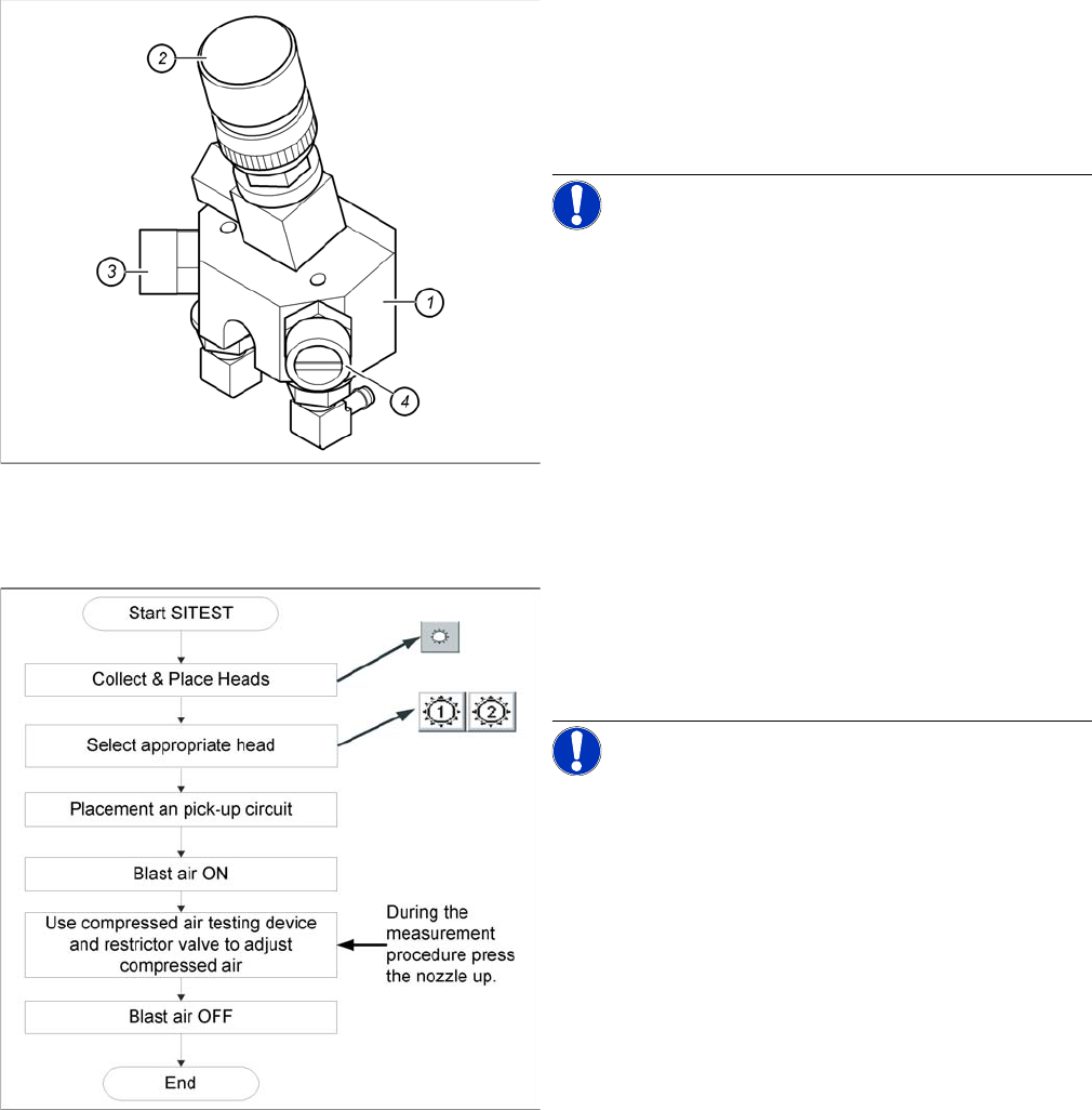
Adjustment of air pressure values
Legend
1. Forced air unit
2. Micro-relay valve
3. Adjustment valve for the reject circuit
4. Adjustment valve for the pick - up / placement circuit
NOTICE! Use a nozzle of type 914 to set the air
blast. Please press in the spring from the nozzle interface
during the measurement and read the value from the dis-
play.
Flow chart determining air pressure values
When setting the air blast value with the compressed air
device and the adjustment valve, observe the following:
► Press the nozzle upwards during the measurement
process!!
NOTICE! The air blast values which are shown
in the Measured Air Blast menu, on the station computer
screen, at Single Functions or in the SITEST program, do
not reflect the air blast values really set at the nozzle.
They solely serve to check that the air blast valve is func-
tioning correctly. Therefore, do not use the values shown
on the screen to set the air blast. Instead, use only the
values determined with the compressed air testing de-
vice.
Settings
C&P12 6.3.12 Performing a Vacuum Test on the C&P 6/12 DLM Heads
218 Service Manual SIPLACE D4/D4i
Repeat these adjustments several times, as the pick - up / placement circuit are mutually dependent.
6.3.12
6.3.12 Performing a Vacuum Test on the C&P 6/12 DLM Heads
Performing a Vacuum Test on the C&P 6/12 DLM Heads
Damage to the valve plunger, silicone hose, the vacuum plate, in or on the nozzle can lead to leakage
which may then cause malfunctions during the placement process or which may reduce the vacuum val-
ue in the holding circuit.
Air Pressure Values Set with compressed air testing de-
vice
Measured at nozzle:
Displayed on the monitor:
(Only in pickup and placement
circuit)
pick - up / placement circuit 150 mbar (100 - 200 mbar) e.g.: 250 mbar
Reject circuit 250 mbar (200 - 300 mbar) Reject circuit does not have a
sensor
NOTICE
The two air blast circuits are controlled via a single valve and therefore influence one another
mutually. However, two different adjustment valves (see items 3 and 4 in the diagram above)
can be used to set the various pressures for each circuit.
NOTICE
Make sure the measurement sensor hose is fitted tightly on the nozzle.
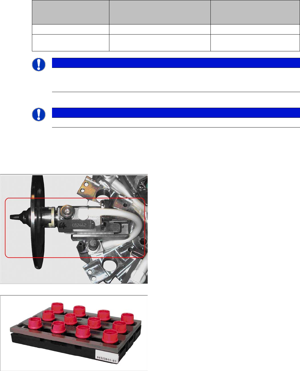
Vacuum test with normal nozzle configuration
▪ The vacuum tests for C&P6/12 in the station software
of the C&P12/6 placement heads only checks the
area from the vacuum generator to the valve plung-
ers.
▪ The area visible here (red frame), from the valve
plunger housing via the silicone hose into the seg-
ment housing and through the sleeve to the nozzle is
not covered by the normal vacuum test.
Equipment required
Closed nozzle tips are required for checking the complete
vacuum circuit.
The special nozzle use for this is marked red and does
not have a nozzle configuration on it:
▪ SOKO nozzle for vacuum test DLM, Item No.
[03067029-01]