SIPLACE D4-D4i 工程师手册_EN.pdf - 第220页
Settings C&P12 6.3.13 Other Mechanical Settings on the Sta r 220 Service Manual SIPLACE D4/D4i Maintenance recommendations: ▪ Use the valve plung er ONLY when greased. (Isoflex topas). ▪ Replacing the valve p lunger …
Settings
6.3.12 Performing a Vacuum Test on the C&P 6/12 DLM Heads C&P12
Service Manual SIPLACE D4/D4i 219
Vacuum test with closed nozzle
► Start SITEST and perform the first reference run, if
required.
► Select the gantry for the required vacuum test on the
C&P6/12 placement head.
► Place all the nozzles for the placement head in the
nozzle changer.
► Replace the full magazine at one magazine position
with the magazine holding the test nozzles
[03067029-01].
► Go to the Nozzle on head for segment 1 menu and
select the nozzle type which was originally configured
for this magazine position.
► Select the checkbox All segments as segment 1
► Pick up the vacuum test nozzles with all segments.
► Select the vacuum test menu and perform a vacuum
test.
► The error message Vacuum difference open/closed
too low can be ignored here.
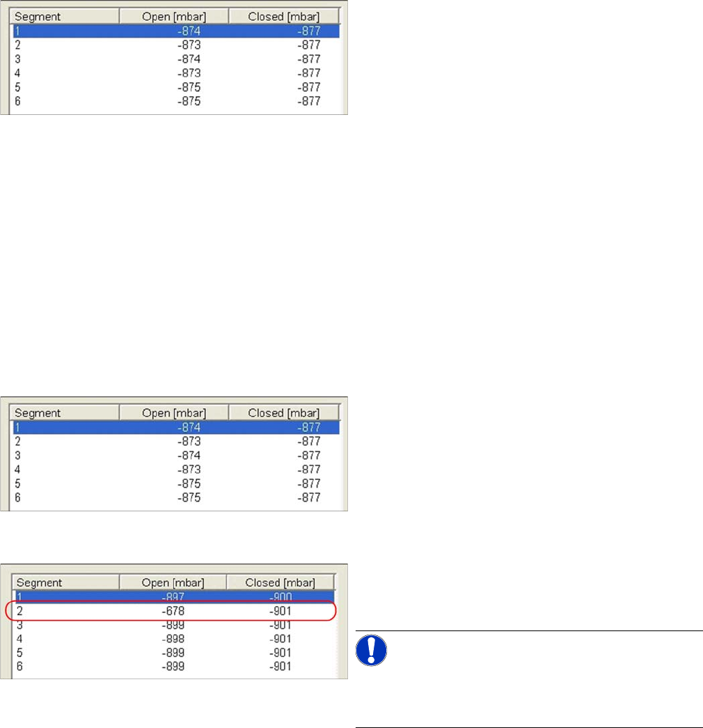
▪ As you can see in the measurement values here, the
Open values deviate by up to 3mbar from the Closed
values.
▪ However, this is within the tolerance of 5 mbar, in
which correct function can be reliably assumed.
► If this tolerance value is exceeded, check the valve
plunger and vacuum plate and replace these a a pre-
caution, if necessary.
Scenario 1
Example of faulty vacuum values, which indicate a dam-
aged vacuum plate at segment 2 here.
NOTICE! Irreparably damaged vacuum plate
If both measurements for a particular segment are
around 640mbar, this indicates that the vacuum plate is
irreparably damaged.
Settings
C&P12 6.3.13 Other Mechanical Settings on the Star
220 Service Manual SIPLACE D4/D4i
Maintenance recommendations:
▪ Use the valve plunger ONLY when greased. (Isoflex topas).
▪ Replacing the valve plunger also means:
– Clean the valve plunger housing! Otherwise good plungers with new grease are installed in the
old, contaminated environment.
– Grease the valve plunger: Use the appropriate tool [03049689-01] to grease the valve plunger.
– Perform vacuum tests with the red SOKO nozzles, vacuum test DLM [03067029-01].
▪ Regularly check the sleeve-nozzle vacuum plate "blue" (available from 10/2008, white) and replace
when necessary (with 1.5mm Allen key).
6.3.13
6.3.13 Other Mechanical Settings on the Star
Other Mechanical Settings on the Star
▪ Set the air blast tube so that it overlaps the circular guide frame by 0.7 mm.
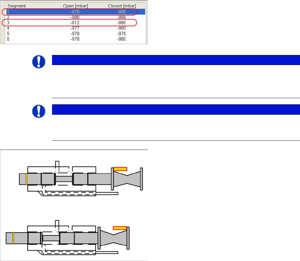
Scenario 2
Example of defective vacuum values, which indicate a
damaged silicone hose on segment 1 and an open nozzle
at segment 3.
NOTICE
Silicone hose defect
Under certain circumstances, silicone hose defects might only be detected when the segments
are moved out. It could therefore be advisable to release the Z axis and to perform a vacuum
test of the segment in its lowered state (single measurement run).
NOTICE
Missing valve plunger
If both measurements for a particular segment are only around 210mbar, this indicates that the
valve plunger is missing.
Vacuum values and valve plunger positions
▪ If the valve plunger is in the position "nozzle open",
the vacuum area will be sealed against the environ-
ment with two seals.
▪ If the valve plunger is in the position "nozzle closed",
the vacuum area (at the rear, near the drive) will be
sealed against the environment with only one seal.
If the "vacuum value closed" is too low, this indicates that
the seal is not sufficiently greased or that it is damaged.
Settings
6.4.1 Component Trolley - Setting the Basic Height Component Handling
Service Manual SIPLACE D4/D4i 221
6.4
6.4 Component Handling
Component Handling
6.4.1
6.4.1 Component Trolley - Setting the Basic Height
Component Trolley - Setting the Basic Height
6.4.1.1
6.4.1.1 Parts, equipment and tools
Parts, equipment and tools
The following tools and equipment are needed to adjust the height of the component trolley:
▪ Set of Allen keys, size 5
▪ Eyebolt with M12 thread to raise the component trolley table,
DIN 580 M12-St [00048350-xx]
▪ Leverage device for raising the component trolley table, must be able to carry at least 80 kg
6.4.1.2
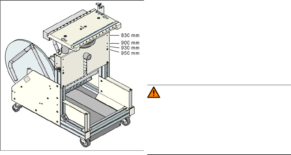
6.4.1.2 Adjusting the Component Trolley to the Board Transport Height
Adjusting the Component Trolley to the Board Transport Height
Component trolley with a PCB conveyor height of
950 mm
▪ Holes drilled for board transport heights 830 -
950 mm in the guidance bars
The component trolley for the S feeder modules can be
easily and quickly adjusted to the following board trans-
port heights:
▪ 830 mm ±15 mm standard height
▪ 900 mm ±15 mm SMEMA height
▪ 930 mm ± 15 mm SMEMA height
▪ 950 mm ±15 mm SMEMA height
WARNING!
The component trolley height may only be set by
SIPLACE technicians or other qualified and officially au-
thorized (certified) personnel.
Observe the applicable accident prevention regulations.
Remove all feeder modules from the changeover table
plate, before you adjust the height of the changeover ta-
ble.