SIPLACE D4-D4i 工程师手册_EN.pdf - 第229页
Settings 6.5.4 Checking the Limit Switch Position Conveyor Service Manual SIPLACE D4/D4i 229 ► The fixed conveyor side of conve yor 2 (right side fixed (track 1 left side fix)) rem ains in its position. ► The ’fixed conv…
Settings
Conveyor 6.5.3 Moving the Fixed Conveyor Edge for ’Extra Wide Conveyor’
228 Service Manual SIPLACE D4/D4i
6.5.2.3
6.5.2.3 Connecting the Dual Conveyor Lifting Tables
Connecting the Dual Conveyor Lifting Tables
► Remove the lifting table plate on conveyor lane 2 in PA1 and on lane 1 in PA2.
► Loosen the lockscrew(s) (4) and use a screwdriver to push the hexagonal circlip over the shaft on
lifting table 1.
► Perform lifting table connection for all placement areas (arrangement rotated by 180°.)
► Configure the new conveyor mode in SIPLACE Pro
6.5.2.4
6.5.2.4 Converting the Single Conveyor Mode Back to Flexible Dual Conveyor Mode
Converting the Single Conveyor Mode Back to Flexible Dual Conveyor Mode
► In the SITEST conveyor menu Options and Configurations, select the menu Change Widening of
Conveyor to set the default conveyor mode.
► The moveable conveyor side of conveyor 1 (right side fixed (track 1 left side fix)) is moved to a small
conveyor width (default).
► The SITEST SW will ask you to disconnect the lifting tables. Do so.
► The SITEST SW will now use the conveyor control SW to move the fixed side of conveyor 2 (right
side is fixed (lane 1 left side fixed)) back to its standard position. Check the distances between the
two fixed conveyor lanes. (see "6.5.2.2 Widening the Conveyor (Flexible Dual Conveyor for Single
Conveyor Mode)" [ ➙ 227])
► Now adjust the conveyor width of both tracks to the required values.
6.5.3
6.5.3 Moving the Fixed Conveyor Edge for ’Extra Wide Conveyor’
Moving the Fixed Conveyor Edge for ’Extra Wide Conveyor’
The standard positions of the fixed conveyor sides are preset.
► In the SITEST conveyor menu Options and Configurations and select the menu Conveyor Excess
Width, to set the conveyor mode "Extra wide".
NOTICE
This option is only a mechanical necessity when you use the dual conveyor as a single convey-
or. The two lifting tables move parallel when they are connected.
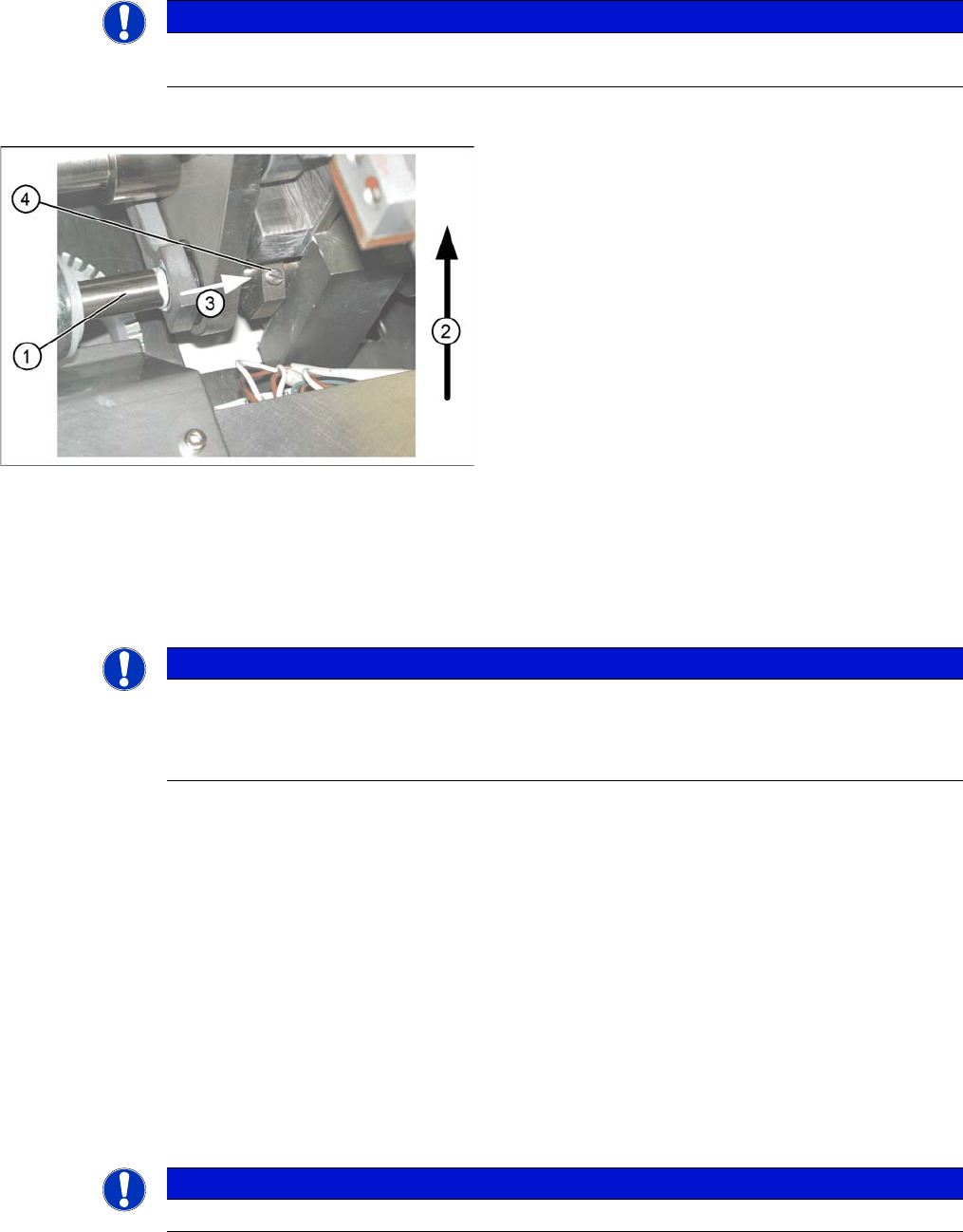
Connecting lifting tables (e.g. PA1 conveyor lane 2)
▪ The drive shaft (1) is connected to the piston rod of
the pneumatic cylinder. This shaft is connected to the
shaft of the lifting table for conveyor lane 1. The lifting
table drive shaft has an additional rod with a hexagon
circlip. This rod is pushed over the shaft of lifting table
1.
▪ Direction of transport (2).
▪ Direction (3) in which the hollow shaft from lifting ta-
ble 2 (1 in PA 2) is to be moved to lifting table 1 (2 in
PA 2).
▪ Lock screws (4).
NOTICE
When converting the dual conveyor to a single conveyor (flexible dual conveyor), connect the
lifting tables when requested to do so by SITEST (we recommend doing this without the com-
pressed air supply to the lifting table).
This function is supported by SIPLACE Pro .
NOTICE
This operating mode is possible for D machines with single or dual conveyors.
Settings
6.5.4 Checking the Limit Switch Position Conveyor
Service Manual SIPLACE D4/D4i 229
► The fixed conveyor side of conveyor 2 (right side fixed (track 1 left side fix)) remains in its position.
► The ’fixed conveyor of track 1(right side fixed (track 2 left side fix)) is moved 34mm to the outside.
This allows you to use wider boards. The flexible conveyor side on lane 2 (lane 1 left fixed) can now
be set to accommodate boards which are wider than 216 mm (242 mm).
6.5.4
6.5.4 Checking the Limit Switch Position
Checking the Limit Switch Position
► Check the minimum and maximum width and ensure that the conveyor edges are parallel.
Values
CAUTION
After the conversion process, you need to measure/calibrate the board reference corner and
the conveyor sides and then save this information in the machine data.
Position of the width adjustment and conv. side limit
switches (symbolic draw)
1. Limit switch on the input conveyor - fitted below the
conveyor edge
2. Limit switch on the input conveyor - fitted below the
conveyor edge
3. Limit switch for the width adjustment unit
4. Transport direction
▪ Limit switches in input conveyor:
There are five limit switches below the conveyor edg-
es near the input conveyor. The limit switch is de-
signed to prevent the conveyor edges hitting one
another or the conveyor frame.
▪ Limit switch in output conveyor:
In the vicinity of the output conveyor there are two
limit switches for the adjustment unit. They serve to
protect the traveling range and initialize (right side)
the adjustment unit for the width adjustment.
Setting Value
Minimum width: 49.7 mm
Maximum width single conveyor: 508.5 mm
Maximum width of dual conveyor 216.5 mm (standard)
Maximum width of dual conveyor 242.5 mm (Standard)
Settings
Conveyor 6.5.5 Width Adjustment Unit
230 Service Manual SIPLACE D4/D4i
6.5.4.1
6.5.4.1 Adjusting the Limit Switch for Initializing the Adjustment Unit
Adjusting the Limit Switch for Initializing the Adjustment Unit
6.5.5
6.5.5 Width Adjustment Unit
Width Adjustment Unit
6.5.5.1
6.5.5.1 Setting the Proximity Switch on the Adjustment Unit
Setting the Proximity Switch on the Adjustment Unit
► When installing the proximity switch, make sure that this is level with the adjustment unit housing.
► The switching point is set via the actuator on the conveyor edge.
► Move the adjustment unit under the conveyor edge, then loosen the actuator using the screw.
► Place the distance gauge 0.2 mm on the adjustment unit, press the actuator against the gauge and
fix with the screw.
► Check the actuators on all conveyor edges and adjust where necessary.
► You then need to calibrate the conveyor edges with the software.
Limit /initialize switch
NOTICE!
This setting is only required after replacing the switch or
other error functions in the width adjustment reference
run.
► Move the adjustment unit for the width adjustment by
hand (via the toothed belt) to the conveyor edge.
► Loosen the two screws on the limit switch (1).
► Move the limit switch in the slot towards the adjust-
ment unit and make sure, that the limit switch is safely
switched on.
► Check the switching state of the corresponding LED
(H11 for TSP 201) (H41 for TSP 301) in the conveyor
control software.
► Fit the limit switch in this position.
► Calibrate the conveyor width via the SITEST pro-
gram.
Overview of the proximity switches on the width adjust
-
ment unit
Legend
1. Short-stroke cylinder
2. Solenoid valve
3. Proximity switch for pneumatic cylinder (for "locking
pin up" recognition)
4. Proximity switch for adjustment unit(for conveyor
edge recognition)
▪ The proximity switch (3) serves as a signal for con-
trolling the pneumatic valve of the adjustment unit.
Once the switching point "conveyor edge present"
has been reached, the conveyor edge is connected
via the pneumatic valve.