SIPLACE D4-D4i 工程师手册_EN.pdf - 第230页
Settings Conveyor 6.5.5 Width Adjustment Unit 230 Service Manual SIPLACE D4/D4i 6.5.4.1 6 . 5 . 4 . 1 A d ju s t in g t h e L im it S w it c h f o r I n itia liz in g t h e A d ju s t m e n t U n it Adjusting the Limit S…
Settings
6.5.4 Checking the Limit Switch Position Conveyor
Service Manual SIPLACE D4/D4i 229
► The fixed conveyor side of conveyor 2 (right side fixed (track 1 left side fix)) remains in its position.
► The ’fixed conveyor of track 1(right side fixed (track 2 left side fix)) is moved 34mm to the outside.
This allows you to use wider boards. The flexible conveyor side on lane 2 (lane 1 left fixed) can now
be set to accommodate boards which are wider than 216 mm (242 mm).
6.5.4
6.5.4 Checking the Limit Switch Position
Checking the Limit Switch Position
► Check the minimum and maximum width and ensure that the conveyor edges are parallel.
Values
CAUTION
After the conversion process, you need to measure/calibrate the board reference corner and
the conveyor sides and then save this information in the machine data.
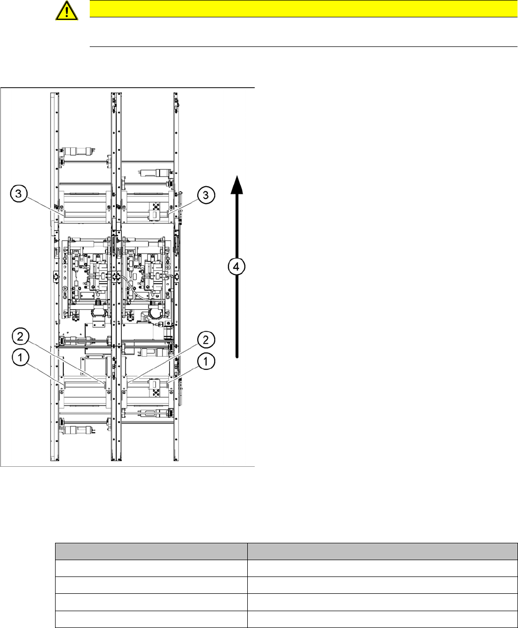
Position of the width adjustment and conv. side limit
switches (symbolic draw)
1. Limit switch on the input conveyor - fitted below the
conveyor edge
2. Limit switch on the input conveyor - fitted below the
conveyor edge
3. Limit switch for the width adjustment unit
4. Transport direction
▪ Limit switches in input conveyor:
There are five limit switches below the conveyor edg-
es near the input conveyor. The limit switch is de-
signed to prevent the conveyor edges hitting one
another or the conveyor frame.
▪ Limit switch in output conveyor:
In the vicinity of the output conveyor there are two
limit switches for the adjustment unit. They serve to
protect the traveling range and initialize (right side)
the adjustment unit for the width adjustment.
Setting Value
Minimum width: 49.7 mm
Maximum width single conveyor: 508.5 mm
Maximum width of dual conveyor 216.5 mm (standard)
Maximum width of dual conveyor 242.5 mm (Standard)
Settings
Conveyor 6.5.5 Width Adjustment Unit
230 Service Manual SIPLACE D4/D4i
6.5.4.1
6.5.4.1 Adjusting the Limit Switch for Initializing the Adjustment Unit
Adjusting the Limit Switch for Initializing the Adjustment Unit
6.5.5
6.5.5 Width Adjustment Unit
Width Adjustment Unit
6.5.5.1
6.5.5.1 Setting the Proximity Switch on the Adjustment Unit
Setting the Proximity Switch on the Adjustment Unit
► When installing the proximity switch, make sure that this is level with the adjustment unit housing.
► The switching point is set via the actuator on the conveyor edge.
► Move the adjustment unit under the conveyor edge, then loosen the actuator using the screw.
► Place the distance gauge 0.2 mm on the adjustment unit, press the actuator against the gauge and
fix with the screw.
► Check the actuators on all conveyor edges and adjust where necessary.
► You then need to calibrate the conveyor edges with the software.
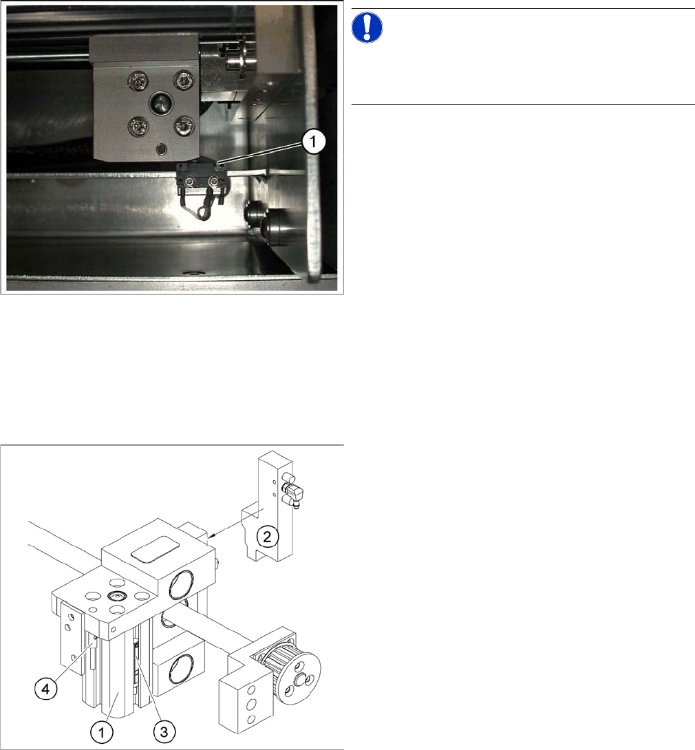
Limit /initialize switch
NOTICE!
This setting is only required after replacing the switch or
other error functions in the width adjustment reference
run.
► Move the adjustment unit for the width adjustment by
hand (via the toothed belt) to the conveyor edge.
► Loosen the two screws on the limit switch (1).
► Move the limit switch in the slot towards the adjust-
ment unit and make sure, that the limit switch is safely
switched on.
► Check the switching state of the corresponding LED
(H11 for TSP 201) (H41 for TSP 301) in the conveyor
control software.
► Fit the limit switch in this position.
► Calibrate the conveyor width via the SITEST pro-
gram.
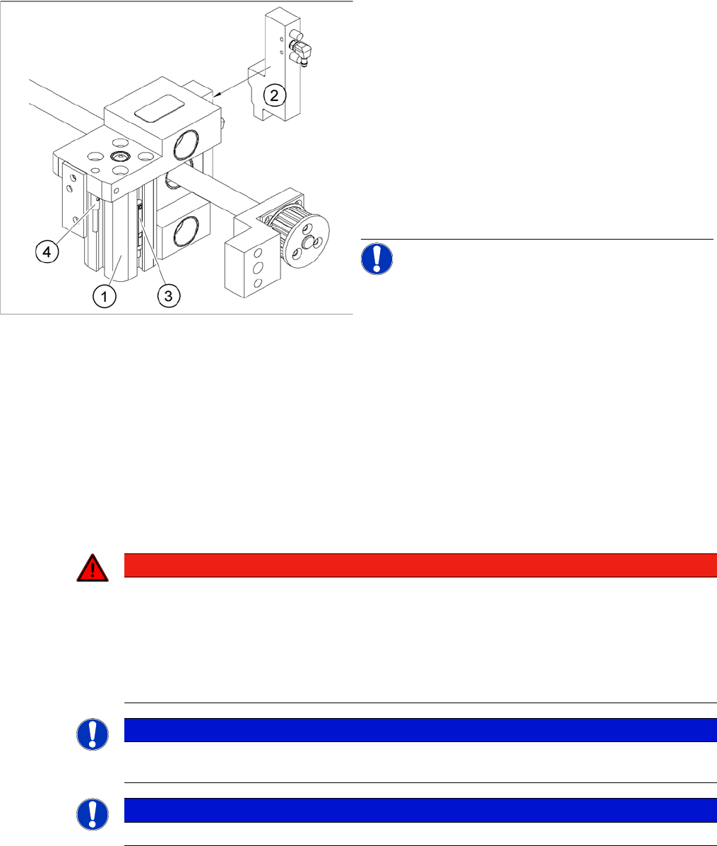
Overview of the proximity switches on the width adjust
-
ment unit
Legend
1. Short-stroke cylinder
2. Solenoid valve
3. Proximity switch for pneumatic cylinder (for "locking
pin up" recognition)
4. Proximity switch for adjustment unit(for conveyor
edge recognition)
▪ The proximity switch (3) serves as a signal for con-
trolling the pneumatic valve of the adjustment unit.
Once the switching point "conveyor edge present"
has been reached, the conveyor edge is connected
via the pneumatic valve.
Settings
6.5.6 Setting the Laser Light Barrier for the Stopper Position Conveyor
Service Manual SIPLACE D4/D4i 231
6.5.5.2
6.5.5.2 Setting the Pneumatic Cylinder Proximity Switch on the Adjustment Unit
Setting the Pneumatic Cylinder Proximity Switch on the Adjustment Unit
► Start SITEST
► Set any conveyor width. The adjustment units are positioned directly under the conveyor edge.
► Start the I/O menu.
► Activate the pneumatic cylinder.
► Set the proximity switch on the pneumatic cylinder so that the LED (H35/H37 for TSP 301) (H64/65
for TSP 201) shines when connected.
6.5.6
6.5.6 Setting the Laser Light Barrier for the Stopper Position
Setting the Laser Light Barrier for the Stopper Position
Overview of the proximity switches on the width adjust
-
ment unit
Legend
1. Short-stroke cylinder
2. Solenoid valve
3. Proximity switch for pneumatic cylinder (for "locking
pin up" recognition)
4. Proximity switch for adjustment unit(for conveyor
edge recognition)
▪ The proximity switch (3) on the adjustment unit cylin-
der should operate when the adjustment unit pin is
pushed out by the pneumatic cylinder and therefore
connected to the conveyor edge. This signal enables
the width adjustment motor.
NOTICE! The proximity switch on the pneumatic
cylinder is set in its engaged state.The proximity switch is
off when the cylinder extended into free space.
DANGER
Laser class 2
The laser light barrier transmitter emits class 2 laser beams. You do not need to take additional
protective measures!
► You should still never look into the laser beam.
► Adjust the LASER diode bean direction only from the rear side of the LASER (left machine
side).
NOTICE
The laser beam deflection has greatest effect at the maximum conveyor width, it should always
be calibrated at the maximum conveyor width.
NOTICE
After setting the laser light barrier you must check or re-teach the PCB reference corner!