SIPLACE D4-D4i 工程师手册_EN.pdf - 第232页
Settings Conveyor 6.5.6 Setting the Laser Light Barrier for the Stopper Position 232 Service Manual SIPLACE D4/D4i Procedure ► Set the maximum conveyor width. ► Choose General functions --> Cycl e mode --> Safety m…
Settings
6.5.6 Setting the Laser Light Barrier for the Stopper Position Conveyor
Service Manual SIPLACE D4/D4i 231
6.5.5.2
6.5.5.2 Setting the Pneumatic Cylinder Proximity Switch on the Adjustment Unit
Setting the Pneumatic Cylinder Proximity Switch on the Adjustment Unit
► Start SITEST
► Set any conveyor width. The adjustment units are positioned directly under the conveyor edge.
► Start the I/O menu.
► Activate the pneumatic cylinder.
► Set the proximity switch on the pneumatic cylinder so that the LED (H35/H37 for TSP 301) (H64/65
for TSP 201) shines when connected.
6.5.6
6.5.6 Setting the Laser Light Barrier for the Stopper Position
Setting the Laser Light Barrier for the Stopper Position
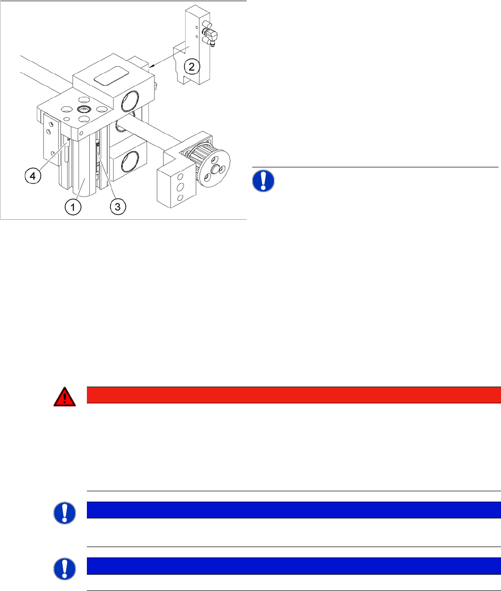
Overview of the proximity switches on the width adjust
-
ment unit
Legend
1. Short-stroke cylinder
2. Solenoid valve
3. Proximity switch for pneumatic cylinder (for "locking
pin up" recognition)
4. Proximity switch for adjustment unit(for conveyor
edge recognition)
▪ The proximity switch (3) on the adjustment unit cylin-
der should operate when the adjustment unit pin is
pushed out by the pneumatic cylinder and therefore
connected to the conveyor edge. This signal enables
the width adjustment motor.
NOTICE! The proximity switch on the pneumatic
cylinder is set in its engaged state.The proximity switch is
off when the cylinder extended into free space.
DANGER
Laser class 2
The laser light barrier transmitter emits class 2 laser beams. You do not need to take additional
protective measures!
► You should still never look into the laser beam.
► Adjust the LASER diode bean direction only from the rear side of the LASER (left machine
side).
NOTICE
The laser beam deflection has greatest effect at the maximum conveyor width, it should always
be calibrated at the maximum conveyor width.
NOTICE
After setting the laser light barrier you must check or re-teach the PCB reference corner!
Settings
Conveyor 6.5.6 Setting the Laser Light Barrier for the Stopper Position
232 Service Manual SIPLACE D4/D4i
Procedure
► Set the maximum conveyor width.
► Choose General functions --> Cycle mode --> Safety mode switch on.
► Activate the relevant laser diode using the input/output functions in SITEST.
► Check the path of the laser beam by covering the front edge of a board with a white label and moving
it into the placement area.
► With the help of the three setting screws, adjust the laser beam to the center of the receiver.
► Check the PCB reference corner and reteach, if necessary.
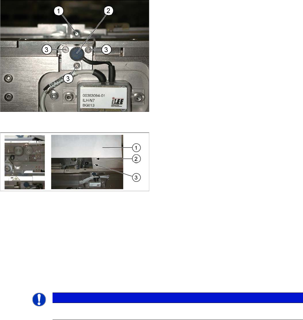
Laser light barrier
Legend
1. Laser receiver
2. Laser diode
3. Setting screws (3x)
Focussing the laser beam
Legend
1. Paper
2. Visible laser beam
3. Board parallel to laser beam
NOTICE
When you move the paper, the beam must follow along the edge of the PCB as accurately as
possible, with minimal deflection to the left and right.
Settings
6.5.7 Function "Constant Transport Time in Placement Area" Conveyor
Service Manual SIPLACE D4/D4i 233
6.5.7
6.5.7 Function "Constant Transport Time in Placement Area"
Function "Constant Transport Time in Placement Area"
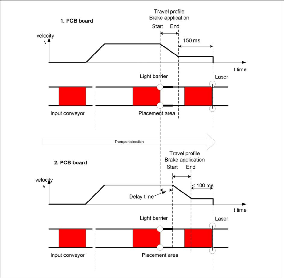
Diagrams of PCB braking
The automatic teaching at the beginning of the travel profile guarantees that the stopper is always
reached in the same time, irrespective of the board weight. The transport time remains the same.
Function:
▪ Switching on the laser light barrier
▪ Starting the board braking procedure.
The light barrier in the placement area is used to recognize the board and then start the braking proce-
dure (travel profile) via the conveyor control software. The software automatically "teaches" the first
board how to move in slow approach mode. Once the travel profile for braking the PCB has begun (on
time), the PCB will be reliably stopped at the laser light barrier, after a maximum of 100ms.
6.5.8
6.5.8 Light Barrier Functions in Input, Intermediate and Output Conveyors
Light Barrier Functions in Input, Intermediate and Output Conveyors
▪ Recognizing and stopping the PCB boards.
▪ Monitoring the boards in the input conveyor i.e.
If a board is recognized in the input conveyor, it will appear on the operating interface and the ma-
chine will lock the conveyor interface to the previous station. When using boards with outbreaks, the
board may stop although the signal of the light barrier is disabled and the interface to the previous