SIPLACE D4-D4i 工程师手册_EN.pdf - 第244页
Settings Conveyor 6.5.12 Conveyor Control TSP 301 244 Service Manual SIPLACE D4/D4i H27 IN Not used H28 IN Not used H29 IN Not used H30 IN Lifting table, placem ent area 1: cylinder switch H31 IN Lifting table, placem en…
Settings
6.5.12 Conveyor Control TSP 301 Conveyor
Service Manual SIPLACE D4/D4i 243
6.5.12.3
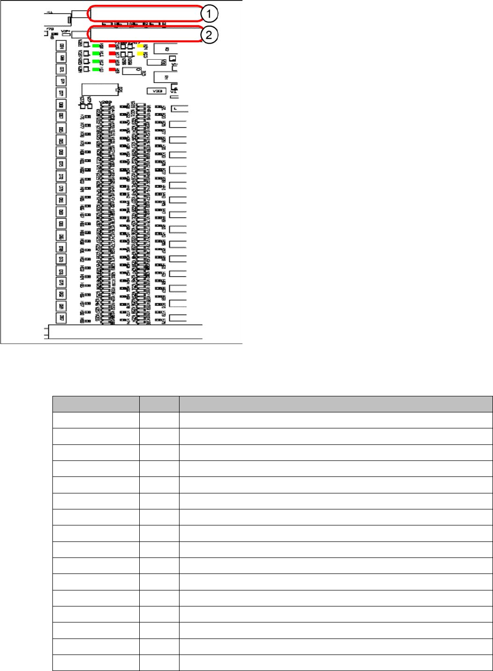
6.5.12.3 LED Display on Conveyor Control TSP 301
LED Display on Conveyor Control TSP 301
6.5.12.4
6.5.12.4 Assignment Table: LEDs on the TSP 301 Conveyor Control
Assignment Table: LEDs on the TSP 301 Conveyor Control
Conveyor Control TSP 301
1. Connector Siemens PCB handling interface up-
stream station lane 1 with corresponding LEDs PCB
handling
2. Connector Siemens PCB handling interface up-
stream station lane 1 with corresponding LEDs PCB
handling
The connector "Siemens PCB handling interface for the
upstream station of lane 2 with corresponding LEDs for
PCB handling" and the connector "PCB handling inter-
face for the downstream station of lane 2 with corre-
sponding LEDs for PCB handling" are located on the
extension board (similar layout).
Anzeige /Display I / O LED assignment
H1 / F1-F5 Fuse F1-F5, Power supply 40 V
H2 / F6 Fuse F6 Power supply 24V
H4(ao) Initializing / control error
H5(ao) CAN bus 1, active
H6(ao) Flashing: program running
H7(ao) CAN bus 2, active (optional)
H9 Out Interference loop
H14 IN Siemens interface for upstream station
H15 IN Siemens interface for downstream station
H20 IN Lifting table placement area 1: forked light barrier A
H21 IN Lifting table placement area 1: forked light barrier B
H22 IN Lifting table placement area 2: forked light barrier A
H23 IN Lifting table placement area 2: forked light barrier B
H24 IN Laser light barrier, placement area 1: receiver
H25 IN Laser light barrier, placement area 2: receiver
H26 IN Not used

Settings
Conveyor 6.5.12 Conveyor Control TSP 301
244 Service Manual SIPLACE D4/D4i
H27 IN Not used
H28 IN Not used
H29 IN Not used
H30 IN Lifting table, placement area 1: cylinder switch
H31 IN Lifting table, placement area 2: cylinder switch
H32 IN Side panel right: limit switch
H33 IN Side panel left: limit switch
H34 IN Width adjustment: limit switch right
H35 IN Not used
H36(ao) IN Width adjustment unit 1: cylinder switch
H37(ao) IN Width adjustment unit 2: cylinder switch
H38(ao) IN Width adjustment unit 1: sensor side panel
H39(ao) IN Width adjustment unit 2: sensor side panel
H40(ao) IN Spindle width adjustment: limit switch right
H41(ao) IN Spindle width adjustment: limit switch left
H42(ao) IN Not used
H43(ao) IN Not used
H44 IN PCB sensor for input conveyor
H45 IN PCB sensor for placement area 1
H46 IN PCB sensor for intermediate conveyor
H47 IN PCB sensor for placement area 2
H48 IN PCB sensor for output conveyor
H49 IN Not used
H50 IN Not used
H51 IN Not used
H52 IN Light scanner "Fluxing", input conveyor
H53 IN Light scanner "Fluxing", placement area 1
H54 IN Light scanner "Fluxing", intermediate conveyor
H55 IN Light scanner "Fluxing", placement area 2
H56 IN Light scanner "Fluxing", output conveyor
H57 IN Not used
H58 IN Option plug placement area 1: input 1
H59 IN Option plug placement area 1: input 2
H60 IN Option plug placement area 1: input 3
H61 IN Option plug placement area 1: input 4
H62 IN Option plug placement area 1: input 5
H63 IN Option plug placement area 1: input 6
H64 IN Option plug placement area 2: input 1
H65 IN Option plug placement area 2: input 2
H66 IN Option plug placement area 2: input 3
H67 IN Option plug placement area 2: input 4
H68 IN Option plug placement area 2: input 5
Anzeige /Display I / O LED assignment

Settings
6.5.12 Conveyor Control TSP 301 Conveyor
Service Manual SIPLACE D4/D4i 245
H69 IN Option plug placement area 2: input 6
H70 Cod. Option plug, placement area 1: coding 1
H71 Cod. Option plug, placement area 1: coding 2
H72 Cod. Option plug, placement area 1: coding 3
H73 Cod. Option plug, placement area 2: coding 1
H74 Cod. Option plug, placement area 2: coding 2
H75 Cod. Option plug, placement area 2: coding 3
H76 Out Lifting table, placement area 1: valve up
H77 Out Lifting table, placement area 1: valve down
H78 Out Lifting table, placement area 2: valve up
H79 Out Lifting table, placement area 2: valve down
H80 Out Laser light barrier, placement area 1: transmitter
H81 Out Laser light barrier, placement area 2: transmitter
H82(ao) Out Width adjustment unit 1: valve
H83(ao) Out Width adjustment unit 2: valve
H84 Out Not used
H85 Out Not used
H86 Out Not used
H87 Out Not used
H88 Out Not used
H89 Out Not used
H90 Out Not used
H91 Out Not used
H92 Out Option plug, placement area 1: output 1
H93 Out Option plug, placement area 1: output 2
H94 Out Option plug, placement area 1: output 3
H95 Out Option plug, placement area 2: output 1
H96 Out Option plug, placement area 2: output 2
H97 Out Option plug, placement area 2: output 3
H98(ao) Out Barcode reader track 1: start signal
H99(ao) Out Barcode reader track 2: start signal
Anzeige /Display I / O LED assignment