SIPLACE D4-D4i 工程师手册_EN.pdf - 第40页
Overview Modular Conveyor 3.5.1 Module Overview 40 Service Manual SIPLACE D4/D4i 3.5 3 . 5 M o d u la r C o n v e y o r Modular Conveyor 3.5.1 3 . 5 . 1 M o d u le O v e r v ie w Module Overview PCB conveyor – single con…
Overview
3.4.2 Cutter Component Handling
Service Manual SIPLACE D4/D4i 39
3.4.2.3
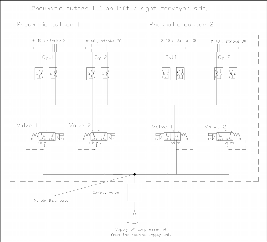
3.4.2.3 Diagrams of Pneumatic System and Functional Sequence
Diagrams of Pneumatic System and Functional Sequence
Diagram of Pneumatic System: Cutter per conveyor edge
Overview
Modular Conveyor 3.5.1 Module Overview
40 Service Manual SIPLACE D4/D4i
3.5
3.5 Modular Conveyor
Modular Conveyor
3.5.1
3.5.1 Module Overview
Module Overview
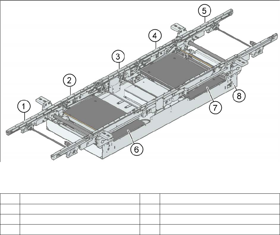
PCB conveyor – single conveyor (D3/D4)
Legend
The modular conveyor system consists of an input conveyor, two placement areas, the intermediate con-
veyor and the output conveyor. Each conveyor system has automatic width adjustment and a lifting table
to clamp the PCB in place. The standard machine is equipped as a single PCB conveyor. A dual PCB
conveyor system is optionally available. Depending on individual requirements, either the left or right
conveyor side can be selected as the fixed conveyor side.
1 Input conveyor 5 Output conveyor
2 Placement area 1 6 Lifting table placement area 1
3 Intermediate belt 7 Lifting table placement area 2
4 Placement area 2 8 Assembly tray
Overview
3.6.1 Overview C&P12
Service Manual SIPLACE D4/D4i 41
3.6
3.6 C&P12
C&P12
3.6.1
3.6.1 Overview
Overview
3.6.1.1
3.6.1.1 Technical Data C&P12
Technical Data C&P12
Technical data C&P12
3.6.1.2
3.6.1.2 Camera Modularity on C&P 12 Head
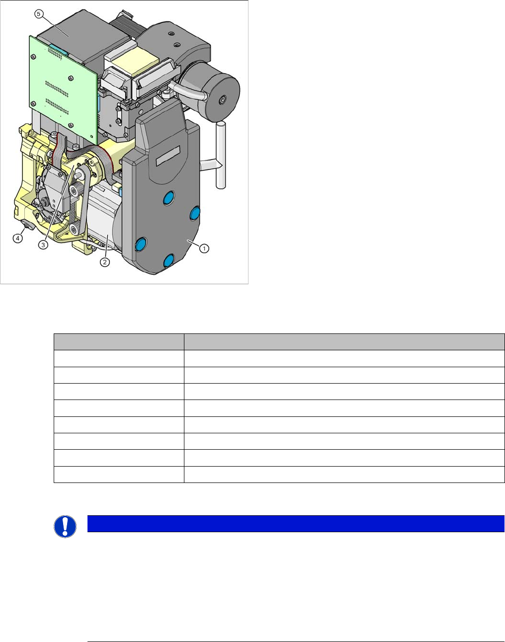
Camera Modularity on C&P 12 Head
The SIPLACE D4/D4i machines have a C&P12 place-
ment head on each gantry. All other D/Di machines per-
mit the use of both C&P6 and C&P12 heads, with the
Head Modularity function.
Legend
1. Intermediate distribution board (under the cover)
2. Star drive
3. Z drive
4. Valve positioning drive
5. Component camera C&P, type 28 (18x18) digital or
type 29 (27x27) digital, high resolution component
camera 18x18 or,optionally, SST29 for 0201
(0.5x0.25 mm) or SST38 from SW 604. or SST30
from SW 605.03SP2
Description 12 segment DLM 3
Component size 1 mm x 0.5 mm (0402)/0.5 mm x 0.25 mm (0201) to 18.7 mm x 18.7 mm
Component height 6.0 mm
Component weight 2.0 g
Placement accuracy +/- 80 µm at 4 (Sigma)
Angular accuracy +/- 0.7° at 4 (Sigma)
Placement force 2.4 - 5.0 N
Nozzle spectrum 901, 904, 905; 911-919; 920-925; 931-937
Nozzle changer Can be set up per magazine or garage
NOTICE
Cause of Hazard
The standard camera on the C&P12 is the 28.sst, although the component camera 29.sst, with
a higher resolution (for small 0201 components), can be installed as an option (the same max-
imum component dimensions apply in this case)
Smaller maximum component dimension apply when using the SST38 camera option. For fur-
ther settings and data for the C&P12 head, see the specifications for the relevant option.
For Di-series (for small 0201 and 01005 components), component camera 30 sst will replace
component camera 29 sst and 38 sst respectively.