SIPLACE D4-D4i 工程师手册_EN.pdf - 第43页
Overview 3.6.1 Overview C&P12 Service Manual SIPLACE D4/D4i 43 Star station 9 ▪ Pickup cycle The nozzle is rotated to the pickup position. ▪ Placement cycle The component is rotated to th e p lacement position (a ngl…
Overview
C&P12 3.6.1 Overview
42 Service Manual SIPLACE D4/D4i
Technical data - component cameras
3.6.1.3
3.6.1.3 Position and Function of Individual Star Stations
Position and Function of Individual Star Stations
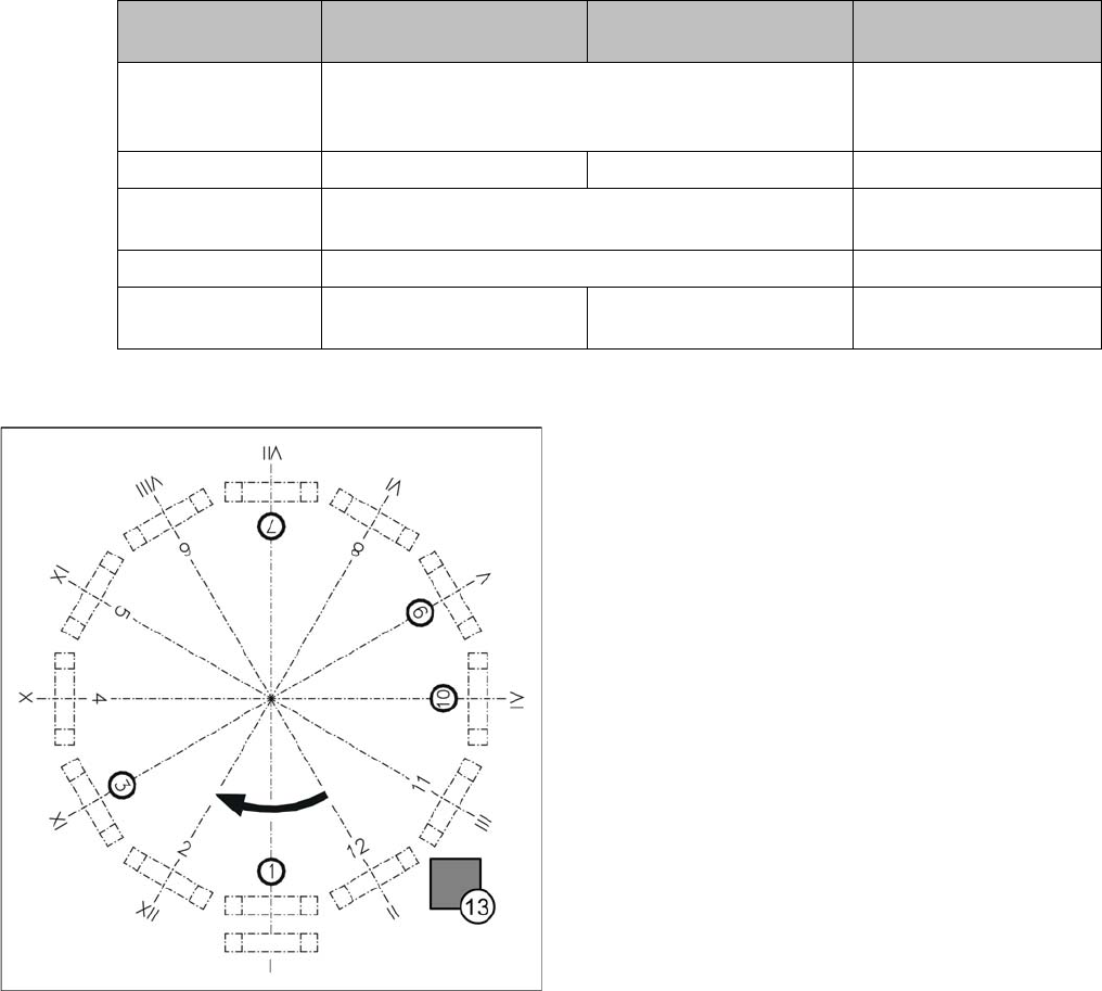
Star station 1
▪ Pickup cycle
The nozzle is lowered onto the component. Once the valve positioning unit has opened the vacuum
circuit to the nozzle, the nozzle draws up the component and removes it from the feeder module.
▪ Placement cycle
The nozzle, together with the component, is lowered onto the PCB that has been moved into place.
The valve positioning unit closes the vacuum channel to the nozzle. A short blast of compressed air
detaches the component from the nozzle and places it on the PCB.
Star station 3
▪ Reject cycle
After the gantry reaches the X and Y reject position, the valve positioning unit closes the vacuum
channel to the nozzle. Defective components are rejected from the nozzle with a short blast of com-
pressed air and are discarded.
Star station 7
▪ The component is optically centered.
Description 12 segment standard
SST 28
12 segment with SST 29 12 segment with SST 30
Component size:
Flip Chip/Bare Die
0.3mm x 0.3 mm (0201) to 18.7 mm x 18.7 mm 0.18mm x 0.18mm
(01005) to 27mm x
27mm
Component height 0.15 mm up to 6 mm 0.15 mm up to 6 mm 0.15 mm up to 6 mm
Placement accura-
cy
+/- 80 µm at 4 (Sigma) +/- 55 µm at 4 (Sigma)
Angular accuracy +/- 0.7° at 4 (Sigma) +/- 0.7° at 4 (Sigma)
Resolution of com-
ponent camera
50µm/pixels 26µm/pixels 17µm/pixels
Legend
I-XII Segment numbering
1. Star station 1: pick up and place component
2. Star station 2: no function
3. Star station 3: reject component
4. Star station 4: no function
5. Star station 5: no function
6. Star station 6: no function
7. Star station 7: optically center component
8. Star station 8: no function
9. Star station 9: rotate component
10. Star station 10: position for removing and inserting
sleeves
11. Star station 11: no function
12. Star station 12: no function
13. Component sensor (optional, between star
stations 11 and 12)
Overview
3.6.1 Overview C&P12
Service Manual SIPLACE D4/D4i 43
Star station 9
▪ Pickup cycle
The nozzle is rotated to the pickup position.
▪ Placement cycle
The component is rotated to the placement position (angle of rotation).
Star station 10
▪ Sleeves can be removed here for maintenance and then reinserted.
Between star station 11&12
▪ Option on 12 nozzle head: The presence and/or height of the component is checked before place-
ment.
3.6.1.4
3.6.1.4 Overview of C&P6/12 Head Parts
Overview of C&P6/12 Head Parts
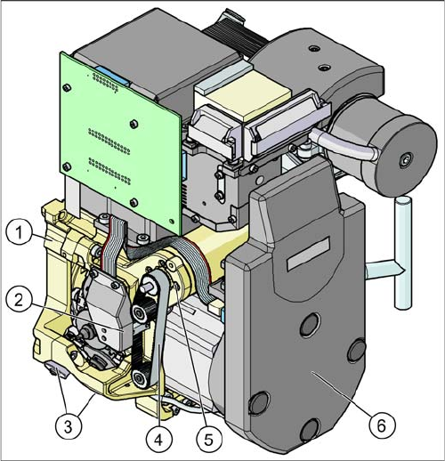
C&P12 head
Legend - overview of parts 1
1. Collect&Place head 12 (DLM3)
[03041228-xx] (shown)
Collect&Place head 6 (DLM3)
[03048341-xx] (not for D4/D4i)
2. Light barrier "Z axis up " (behind the cover)
[00347297-xx]
3. Placement circuit valve positioning drive
[00368076-xx]
Reject circuit valve positioning drive
[00368074-xx]
4. Z axis toothed belt
[00334936-xx]
5. Z axis drive
[03038908-xx]
6. Intermediate distributor, digital (behind the cover)
[00330648-xx]
Overview
C&P12 3.6.1 Overview
44 Service Manual SIPLACE D4/D4i
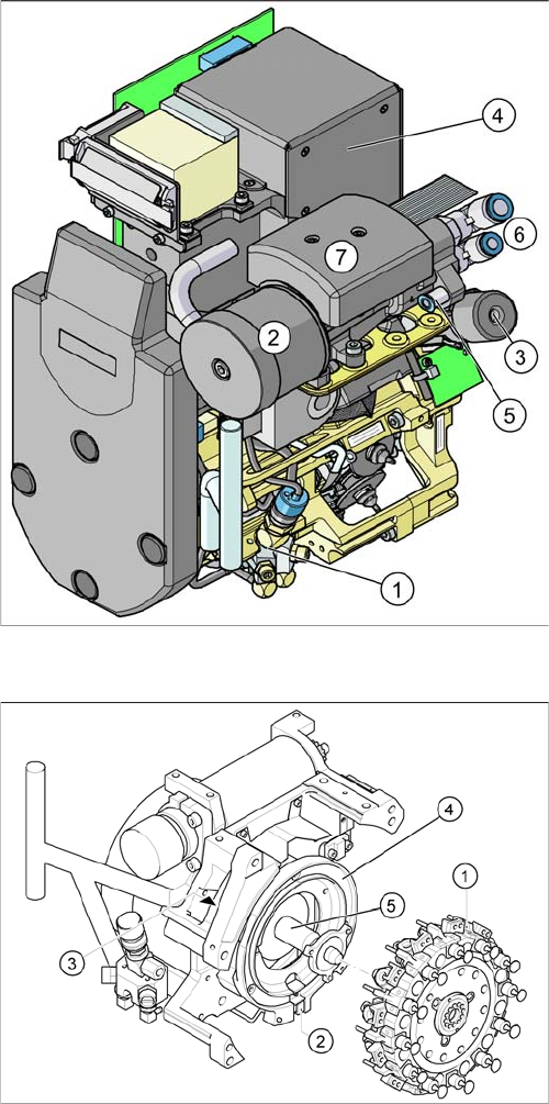
C&P12 head
Legend - overview of parts 2
1. Forced air unit with electromagnetic valve (version 02
– backwards compatibility)
[00367793-xx]
2. Silencer
[03003134-xx]
3. Turning station
[00341780-xx]
4. Component camera 18x18
[03014449-xx]
Component camera 27x27(sst29)
[03018637-xx]
Component camera 27x27(sst30)
[03085394-xx] (for Di-series)
5. Compressed air connection for forced air unit
6. Compressed air supply for vacuum generator (hold
circuit and pickup/place)
7. Vacuum measuring board (under the cover)
C&P12 head
Legend - overview of parts 3
1. Star, Fitted
2. "Z axis down" sensor
3. RSF digital encoder 12/DLM2
4. Circular arc guide (raceway), aligned to star drive
axis
5. Star drive axis, centered by head housing and Z axis
claw