SIPLACE D4-D4i 工程师手册_EN.pdf - 第44页
Overview C&P12 3.6.1 Overview 44 Service Manual SIPLACE D4/D4i C&P12 head Legend - overview of parts 2 1. Forced air unit with electrom agnetic va lve (version 02 – backwards compatibility) [00367793-xx] 2. Silen…
Overview
3.6.1 Overview C&P12
Service Manual SIPLACE D4/D4i 43
Star station 9
▪ Pickup cycle
The nozzle is rotated to the pickup position.
▪ Placement cycle
The component is rotated to the placement position (angle of rotation).
Star station 10
▪ Sleeves can be removed here for maintenance and then reinserted.
Between star station 11&12
▪ Option on 12 nozzle head: The presence and/or height of the component is checked before place-
ment.
3.6.1.4
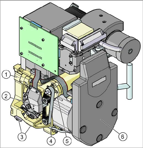
3.6.1.4 Overview of C&P6/12 Head Parts
Overview of C&P6/12 Head Parts
C&P12 head
Legend - overview of parts 1
1. Collect&Place head 12 (DLM3)
[03041228-xx] (shown)
Collect&Place head 6 (DLM3)
[03048341-xx] (not for D4/D4i)
2. Light barrier "Z axis up " (behind the cover)
[00347297-xx]
3. Placement circuit valve positioning drive
[00368076-xx]
Reject circuit valve positioning drive
[00368074-xx]
4. Z axis toothed belt
[00334936-xx]
5. Z axis drive
[03038908-xx]
6. Intermediate distributor, digital (behind the cover)
[00330648-xx]
Overview
C&P12 3.6.1 Overview
44 Service Manual SIPLACE D4/D4i
C&P12 head
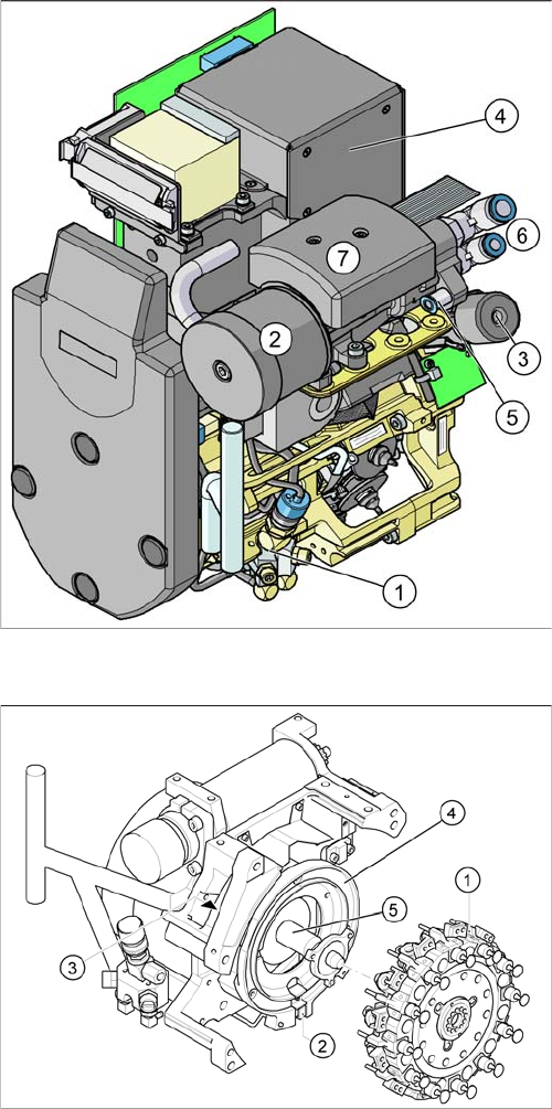
Legend - overview of parts 2
1. Forced air unit with electromagnetic valve (version 02
– backwards compatibility)
[00367793-xx]
2. Silencer
[03003134-xx]
3. Turning station
[00341780-xx]
4. Component camera 18x18
[03014449-xx]
Component camera 27x27(sst29)
[03018637-xx]
Component camera 27x27(sst30)
[03085394-xx] (for Di-series)
5. Compressed air connection for forced air unit
6. Compressed air supply for vacuum generator (hold
circuit and pickup/place)
7. Vacuum measuring board (under the cover)
C&P12 head
Legend - overview of parts 3
1. Star, Fitted
2. "Z axis down" sensor
3. RSF digital encoder 12/DLM2
4. Circular arc guide (raceway), aligned to star drive
axis
5. Star drive axis, centered by head housing and Z axis
claw
Overview
3.6.1 Overview C&P12
Service Manual SIPLACE D4/D4i 45
3.6.1.5
3.6.1.5 Compressed Air Supply - C&P Head
Compressed Air Supply - C&P Head
Vacuum Generator
Placement Head Function Check
Before the 1st reference run or with released Z and star axis:
Check Z axis:
▪ Rotate the star so that one segment is in the star pickup/place position.
▪ Position the Z axis up and down on the belt. The LED light barrier (LB) Z up will shine (down) or ex-
tinguish (up).
▪ Position the Z axis downwards, touch the nozzle tip and press upwards. The LB 'Z down' will shine
and both LEDs will shine until the Z axis is pulled up again.
Check the stepping motor for swiveling in the turning station:
▪ Touch the turning station cam disk on the right side of the head with your finger and rotate it. The 'LB
DP' LED will shine and extinguish with the scan rhythm of the cam disk.
Check the stepping motors of the valve positioning drives:
▪ Feel along the bottom of the placement head from the right side and touch the cam disk upwards in
the pickup/place position.
▪ When rotated, the LB "ZH" shines and extinguishes with the scan rhythm of the cam disk.
▪ Feel along the bottom of the placement head from the left side and touch the cam disk upwards in
the reject position.
▪ When rotated, the LB "BA" shines and extinguishes with the scan rhythm of the cam disk.
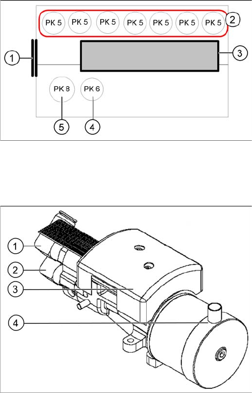
Pneumatic distributor under the gantry head distributor
(symbolic side view from the right)
The placement head is supplied with 4.5 bar compressed
air from the pneumatic unit. The 7-fold pneumatic hose is
also used to cool the Y-axis motor.
Legend
1. Input: Discharged air Venturi nozzle pneumatic hose
(PK12)
2. Input: 7-fold pneumatic hose (PK 5)
3. Silencer for discharged air
4. Compressed air for the pickup / placement circuit
(PK6)
5. Compressed air for hold circuit (PK8)
Vacuum generator
Legend
1. Hold circuit supply
2. Placement and pickup circuit for blast air supply
3. Vacuum measuring board
4. Discharged air from the vacuum generator to the si-
lencer in the compressed air distributor