SIPLACE D4-D4i 工程师手册_EN.pdf - 第55页
Service Work 4.1.2 Measuring the Power Supply Unit Electrical System Service Manual SIPLACE D4/D4i 55 4.1.2.3 4 . 1 . 2 . 3 M e a s u r in g v o lt a g e s a t t r a n s f o r m e r T 1 Measuring voltages at transformer …
Service Work
Electrical System 4.1.2 Measuring the Power Supply Unit
54 Service Manual SIPLACE D4/D4i
Measuring voltages at main power filter Z1 and electrolytic capacitor C1
The diagram above shows the position of the power supply filter and the electrolytic capacitor C1.
▪ 4 main power filters for 36 A 3-phase systems
▪ 10 electrolytic capacitors 33000 µF / 63 V
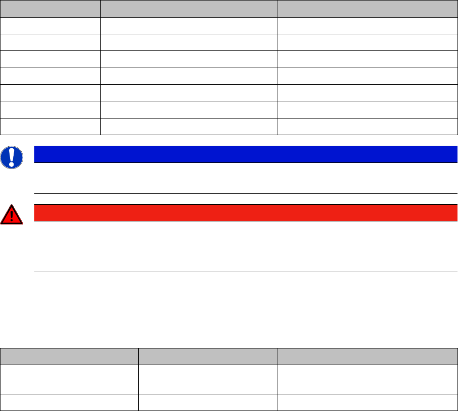
Rectifiers Input Output
V1 3 x 140 VAC 200 VDC
V2 150 VDC 150 VDC
V3 3 x 32.5 VAC 40 VDC
V4 3 x 32.5 VAC 40 VDC
V5 3 x 8.14 VAC 8 VDC
V6 3 x 40.7 VAC 48 VDC
V7 3 x 24.4 VAC 24 VDC
NOTICE
► Remember to replace the perspex safety panels over rectifiers V1 and V7 when the meas-
urements are complete.
DANGER
RISK OF DEATH BY ELECTRIC SHOCK
► Switch the placement system off at the main switch.
► Disconnect the placement system from the power supply.
Assembly Terminal Voltages
Main power filter Z1 L1, L2, L3 3 x 204 V~ / 3 x 230 V~ / 3 x 380 V~ /
3x400V~ / 3x415V~
Electrolytic capacitor C1 + / - 52 VDC
Service Work
4.1.2 Measuring the Power Supply Unit Electrical System
Service Manual SIPLACE D4/D4i 55
4.1.2.3
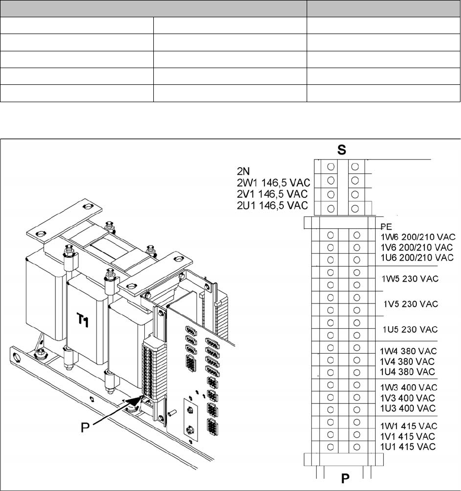
4.1.2.3 Measuring voltages at transformer T1
Measuring voltages at transformer T1
Primary side of transformer T1
The transformer can be connected to the following main power supplies:
3 x 230 VAC for the "on-board electrical system" is drawn at terminals 1U5, 1V5 and 1W5. This is used
to supply the PC and the monitor.
Primary terminals of transformer T1
Voltage Terminals
3 x 200-210 V~ (U.S.A) ± 5 %, 50/60 Hz 1U6, 1V6, 1W6
3 x 230 VAC ± 5 %, 50/60 Hz 1U5, 1V5, 1W5
3 x 380 VAC ± 5 %, 50/60 Hz 1U4, 1V4, 1W4
3 x 400 VAC (Europe) ± 5 %, 50/60 Hz 1U3, 1V3, 1W3
3 x 415 VAC ± 5 %, 50/60 Hz 1U1, 1V1, 1W1
Service Work
Electrical System 4.1.2 Measuring the Power Supply Unit
56 Service Manual SIPLACE D4/D4i
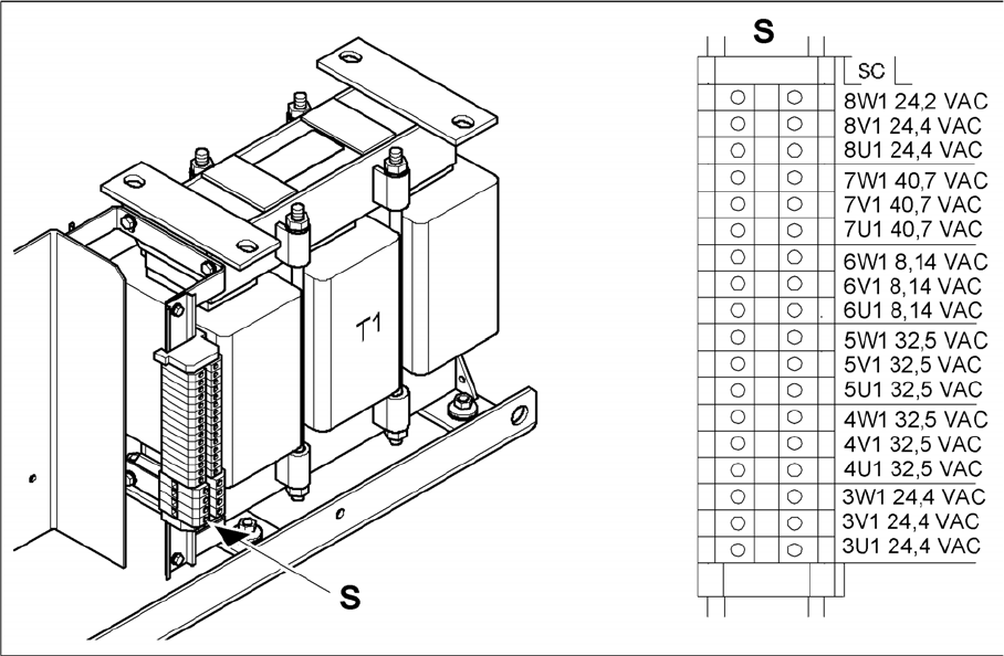
Secondary side of transformer T1
Secondary terminals of transformer T1
Transformer T1 supplies the following voltages on the secondary side:
▪ 3 x 24.4 VAC
▪ 3 x 40.7 VAC
▪ 3 x 8.14 VAC
▪ 3 x 32.5 VAC
▪ 3 x 32.5 VAC
▪ 3 x 24.4 VAC