SIPLACE D4-D4i 工程师手册_EN.pdf - 第61页
Service Work 4.2.2 Replacing the Elastomeric Spring [00301040-01] Gantry Service Manual SIPLACE D4/D4i 61 ► Switch off t he motor contactor i n the power supply and secure i t with a pa dlock. 4.2.2 4 . 2 . 2 R e p la c …
Service Work
Gantry 4.2.1 Preparations for Service Work
60 Service Manual SIPLACE D4/D4i
Firmware download
Replacing the Servo Card
4.2
4.2 Gantry
Gantry
4.2.1
4.2.1 Preparations for Service Work
Preparations for Service Work
► End all placement operations on the placement system.
► Disconnect the changeover table of the gantry concerned, if necessary.
► Switch the placement system off at the main switch.
► Wait until the operating system has shut down and the UPS has switched off.
► Disconnect the machine from the power supply.
► Disconnect the placement system from the compressed air supply.
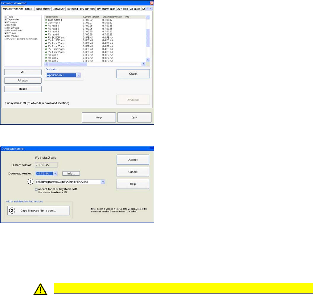
Overview of firmware download
► Start SITEST.
► Download the firmware for the relevant axes. To do
this, select "Settings" from the SITEST menu bar and
then "Firmware Download".
Firmware download
In the CAN FW folder there are all current Firmware ver-
sions of all axes, tables etc.
Legend
1. The system checks this folder, to see whether there
is a newer version of the firmware for the respective
axis, table etc.. If there exist a new firmware version,
this new version will be offered and could be down-
loaded for example to the star- axis.
2. You can also copy a new firmware version manually
into the CAN FW folder. Click on Copy firmware file to
pool. An Explorer menu will open, in which you can
directly copy the new firmware version from a USB
stick etc. into the CAN FW folder. The firmware ver-
sion you selected will now be available in the selec-
tion menu (see item (1)).
CAUTION
TBS servo for the star axis of the DLM3 head.
Service Work
4.2.2 Replacing the Elastomeric Spring [00301040-01] Gantry
Service Manual SIPLACE D4/D4i 61
► Switch off the motor contactor in the power supply and secure it with a padlock.
4.2.2
4.2.2 Replacing the Elastomeric Spring [00301040-01]
Replacing the Elastomeric Spring [00301040-01]
4.2.2.1
4.2.2.1 Tools and Equipment
Tools and Equipment
▪ Set of DIN 911 Allen keys
4.2.2.2
4.2.2.2 Parts
Parts
▪ Elastomeric spring 25 x 10.5 x 50 [00301040-01]
4.2.2.3
4.2.2.3 Removing the elastomeric spring
Removing the elastomeric spring
► Switch the machine off and secure it to prevent unauthorized reactivation as described in "4.2.1
Preparations for Service Work" [ ➙ 60].
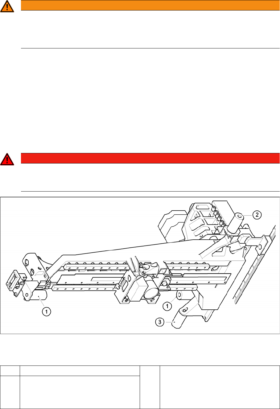
Replacing the elastomeric spring
Legend
► Loosen the M8x20 hexagon socket-head screw in the drilling in the elastomeric spring.
WARNING
To avoid damaging the Collect&Place head, ALWAYS observe the following points when mov-
ing the gantry:
► NEVER move the gantry by pushing with your hands against the Collect&Place head.
► NEVER push the gantry while the Z axis is lowered.
DANGER
POWERFUL MAGNETIC FIELD
► Always follow the special safety instructions when working in the vicinity of powerful mag-
netic fields (see section).
1 Elastomeric spring for X-axis 3 All gantries: elastomeric spring for Y-axis
2 Gantries 1 and 3: elastomeric spring for the
Y-axis
Gantries 2 and 4: bracket instead of elasto-
meric spring

Service Work
Gantry 4.2.3 Replacing the X Axis Scale [00329316-01]
62 Service Manual SIPLACE D4/D4i
4.2.2.4
4.2.2.4 Installing the elastomeric spring
Installing the elastomeric spring
► Use the M8 x 20 hexagon socket-head screw to fix the elastomeric spring.
4.2.2.5
4.2.2.5 Settings
Settings
None
4.2.3
4.2.3 Replacing the X Axis Scale [00329316-01]
Replacing the X Axis Scale [00329316-01]
4.2.4
4.2.4 Replacing the Y-Axis Scale
Replacing the Y-Axis Scale
4.2.5
4.2.5 Replacing the Tensioning Keys [00329478-01, 00329485-01]
Replacing the Tensioning Keys [00329478-01, 00329485-01]
4.2.5.1
4.2.5.1 Tools and Equipment
Tools and Equipment
▪ Set of DIN 911 Allen keys
▪ Belt tension measuring device TSM [00326015-01]
▪ "Measuring belt tensions" operating instructions
4.2.5.2
4.2.5.2 Parts
Parts
▪ Tensioning key [00329478-01]
▪ Tensioning key [00329485-01]
4.2.5.3
4.2.5.3 Removing the tensioning keys
Removing the tensioning keys
► Switch the machine off and secure it to prevent unauthorized reactivation as described in "4.2.1
Preparations for Service Work" [ ➙ 60].
► Push the head mount in the direction of the deflection pulley (6).
► To relax the toothed belt (5), proceed as follows:
⇨ Loosen the locknut (11),
⇨ Turn the hexagon socket-head screw (3) counterclockwise.
Removing the tensioning key, item 1 (synchronizing disk, short)
► Loosen the M4 x 5 hexagon socket-head screw (8).
► Lift out the tensioning key.
Removing the tensioning key, item 2 (synchronizing disk, long)
► Rotate the hexagon socket-head screw (3) out of the spacer bolt (7).
► Lift out the tensioning key.
NOTICE
This service task may only be performed by specially trained service technicians from SIE-
MENS. The procedure is described in a separate manual.
NOTICE
This service task may only be performed by specially trained service technicians from SIE-
MENS. The procedure is described in a separate manual.