SIPLACE D4-D4i 工程师手册_EN.pdf - 第84页
Service Work Component Handling 4.3.2 Cutter 84 Service Manual SIPLACE D4/D4i ► Rem ove the co ver from the contro l board (14) . ► Unplug the press-fit connec tion of the power supply and the drive from the con trol boa…
Service Work
4.3.2 Cutter Component Handling
Service Manual SIPLACE D4/D4i 83
*) Loosen these screws only when removing/installing the cutter.
See also
6.4.3 Check the gap between the empty-tape baffle, inside and the leading edge of the tape deflec-
tor. [ ➙ 223]
4.3.2.14 Final Steps [ ➙ 107]
Tightening Torques for Cutter Screws
4.3.2.5
4.3.2.5 Exchanging the Pneumatic Cutter
Exchanging the Pneumatic Cutter
Removing the Cutter
Thread Tightening torque (Nm)
M3 1.0 – 1.3
M4 2.7 – 3.0
M5 5.5 – 6.0
M6 9.5 – 10.2
WARNING
► Wear thick protective gloves
► When removing the cutter, hold it only on the left and right, on the outside.
► Turn the machine and then the flow of compressed
air ON.
► Disconnect the movable changeover table from the
machine and move it out of the machine.
► Switch off the supply of compressed air at the com-
pressed air unit and actuate the needle valve on the
compressed air unit to bleed the compressed air
lines.
► Turn the machine OFF, disconnect the machine from
the line and turn off the flow of compressed air at the
compressed air unit.
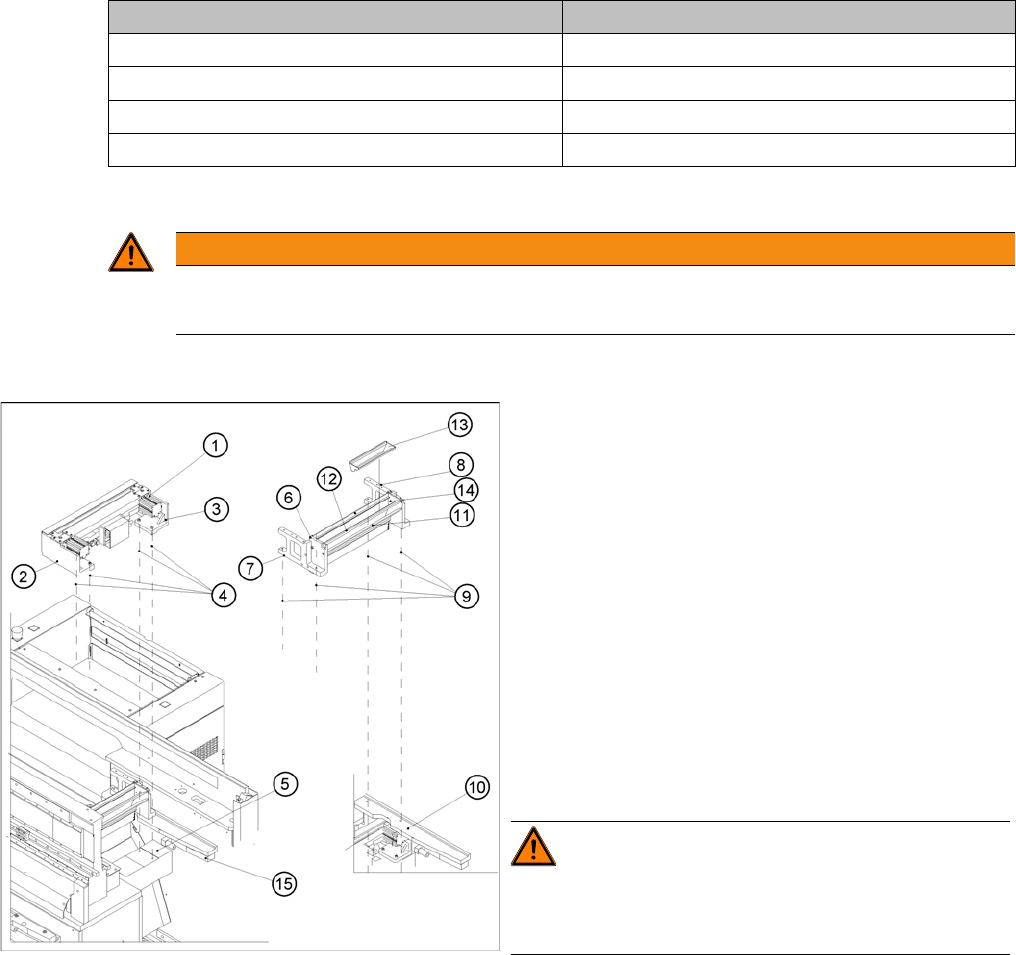
► Loosen the screws fastening the empty-tape duct as-
sembly (6) (M6x35), lift the empty-tape duct and
place it carefully down on the PCB conveyor. The
nozzle changer remains fixed to the empty-tape duct.
WARNING! There is always a risk of injuring
yourself on the cutting edge of the blades.
For this reason, the deflector plate, the cover and the pro-
tective sheet must be left in place.
► Undo the fixtures for the stop buffer assembly (15)
(two hexagon-socket head screws M8x25 on each
side) on the left and right-hand sides of the machine
base, under the surface supporting the changeover
table.
Service Work
Component Handling 4.3.2 Cutter
84 Service Manual SIPLACE D4/D4i
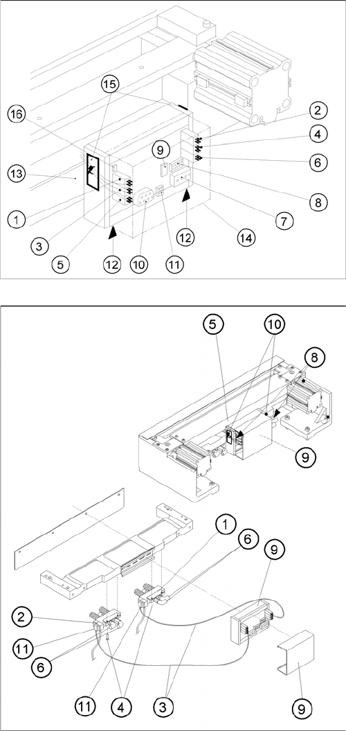
► Remove the cover from the control board (14).
► Unplug the press-fit connection of the power supply
and the drive from the control board (11, 10).
► Remove the cover from the cable duct (5).
► Disconnect the compressed air connection (9) (Y
socket union) for the cutter in the cable duct (5).
► Unplug the plug-and-socket connection of the power
supply and the drive on the control board (see -> 11,
10).
► Carefully undo the corresponding cable tie (10) on
the outside of the control board box.-> Do not dam-
age the cables in this process.
Service Work
4.3.2 Cutter Component Handling
Service Manual SIPLACE D4/D4i 85
Installing the Cutter
► Make sure that the following warning signs are on the cover plate over the moveable blade (see op-
erating manual) and, if they are not, attach them:
⇨ Adhesive Label with text " Disconnect machine from line voltage and....",
⇨ Adhesive Label: Triangle warning symbol "Hand injury".
WARNING! The area under the cutter must be
clear.
(e.g., do not place your feet under it either).
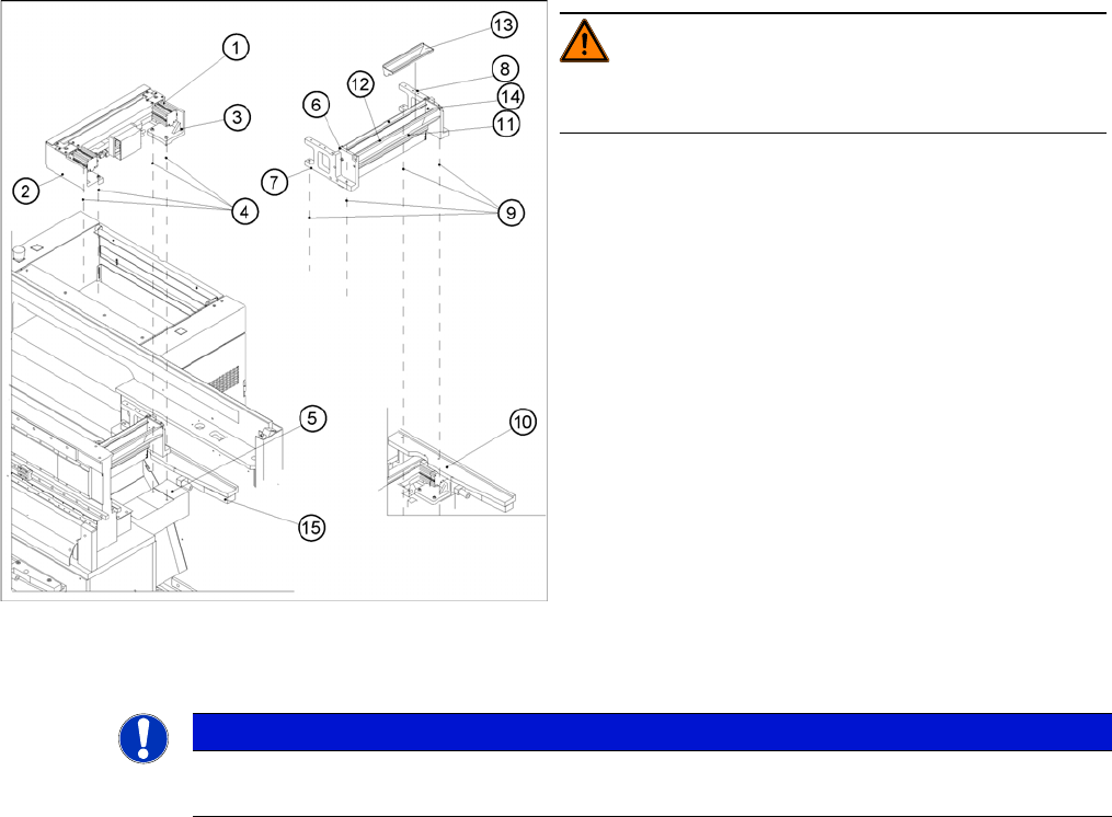
► Loosen the screws fastening the cutter to the ma-
chine base
2 M6x25 screws each (4), on the left (2) and right cut-
ter holders (3).
⇨ In exceptional cases, disks or plates may have
been installed between the contact surface of the
cutter on the machine base and the cutter itself.
-> Save these disks / plates and re-install them lat-
er.
► Securely hold the cutter tight at both ends.
► Pull the cutter out away from the contact surfaces (on
the machine base) towards the outside of the ma-
chine (towards your body).
► Set the cutter down such that it does not pose a risk
of injury to uninvolved personnel either. Put it in its
own crate / container immediately.
NOTICE
► If you are installing a new cutter, remove any excess oil or lubrication grease, before instal-
lation.