SIPLACE D4-D4i 工程师手册_EN.pdf - 第87页
Service Work 4.3.2 Cutter Component Handling Service Manual SIPLACE D4/D4i 87 See also 4.3.2.4.1 Tighte ning Torques for Cutter Screws [ ➙ 83] 6.4.3 Check the gap between th e empty-tape baffle, inside an d t he …
Service Work
Component Handling 4.3.2 Cutter
86 Service Manual SIPLACE D4/D4i
CAUTION! Tighten the screws to the correct
torque.
► If there were disks or plates inserted between the
contact surface of the cutter on the machine base and
the cutter itself, re-install them now.
⇨ The cutter must be shimmed to the same height at
all 4 contact points.
► In the reverse order to disassembly, place the new
pneumatic cutter on the contact surfaces of the ma-
chine base and push it in to the fixture position.
► To avoid dropping the cutter, insert all 4 M6 screws
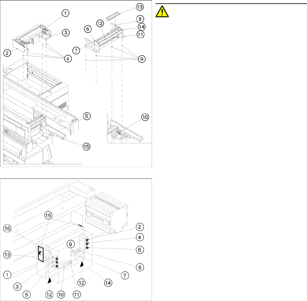
(4) into the holes now:
► Pull the cutter as far as possible away from the PCB
conveyor for the time being.
► Snug up the screws somewhat for the time being.
► Remove the cover (14) from the control board of the
new cutter.
► Plug the press-fit connection of the power supply and
the drive into the control board (11, 10).
► Use a cable tie to fasten the cables running to the ca-
ble duct to the fixing pedestal on the control board
box.
⇨ Make sure that there is no strain on the cable/
press-fit connections
Service Work
4.3.2 Cutter Component Handling
Service Manual SIPLACE D4/D4i 87
See also
4.3.2.4.1 Tightening Torques for Cutter Screws [ ➙ 83]
6.4.3 Check the gap between the empty-tape baffle, inside and the leading edge of the tape deflec-
tor. [ ➙ 223]
4.3.2.4 Overview of Cutter [ ➙ 82]
3.4.2.2 Overview: Mechanical Construction [ ➙ 38]
4.3.2.6
4.3.2.6 Turning the Stationary and Moveable Blade by 180 °
Turning the Stationary and Moveable Blade by 180 °
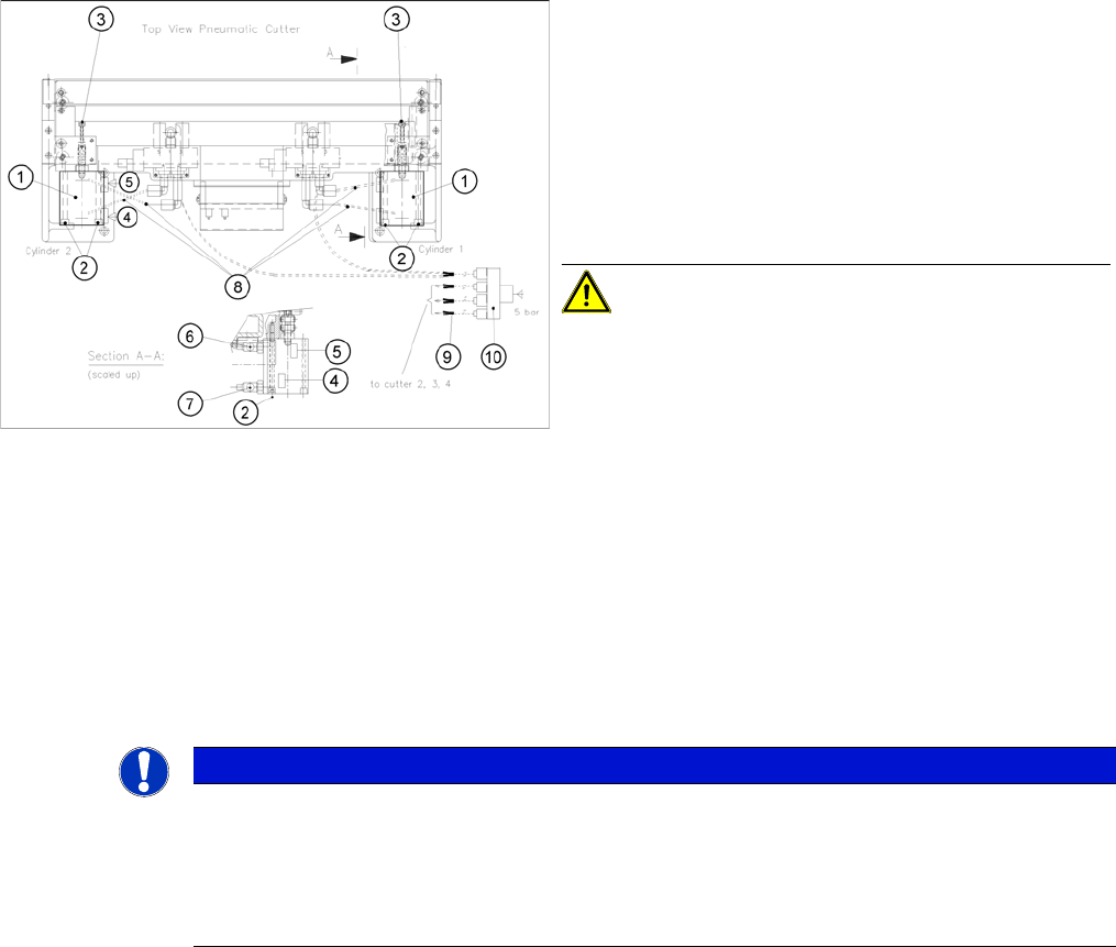
► Plug the compressed air connection to the machine
into the Y socket union (9) (in the cable duct).
► Place the cover back on the control board and the ca-
ble duct.
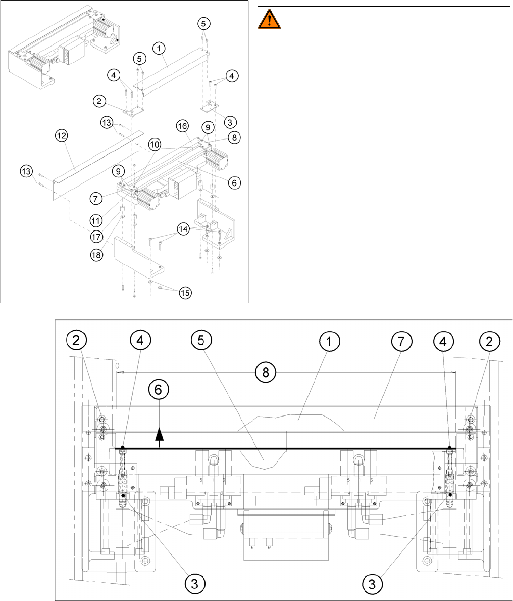
► Fit the empty-tape duct assembly and check the gap
between the empty-tape baffle, inside and the leading
edge of the tape deflector.
► In this position tighten all 4 screws crosswise.
CAUTION! Tighten the screws to the correct
torque.
► Perform the appropriate “Final Steps”.
NOTICE
The movable blade has a cutting edge on both sides.
If one cutting edge becomes worn, the blade can still be used by turning it 180° on its vertical
axis and reinstalling it.
At the same time, the stationary blade must also be turned 180° on its vertical axis and installed.
If both edges are already blunt, replace the blades.
Service Work
Component Handling 4.3.2 Cutter
88 Service Manual SIPLACE D4/D4i
Removing the Blades
Removing/fitting the stationary and movable blade
WARNING! Risk of injury!
There is a high risk of injury from the blades and the tape
deflector.
Wear appropriately thick protective gloves!
Never reach into the cutter from below or into the empty-
tape duct from above.
Make sure that no-one can injure themselves on the cut-
ter, after it has been dismantled and placed next to the
machine!
► Remove the cutter.(See "4.3.2.5 Exchanging the
Pneumatic Cutter" [ ➙ 83].)
► Dismantle the deflector plate (12): 4 hexagon socket-
head screws M4 x 8 (13).