SIPLACE D4-D4i 工程师手册_EN.pdf - 第89页
Service Work 4.3.2 Cutter Component Handling Service Manual SIPLACE D4/D4i 89 Legend ► Loosen the screws fastening the s tationary bla de on the left an d right (2) . ► Mark the mounting position of the stationary blade …
Service Work
Component Handling 4.3.2 Cutter
88 Service Manual SIPLACE D4/D4i
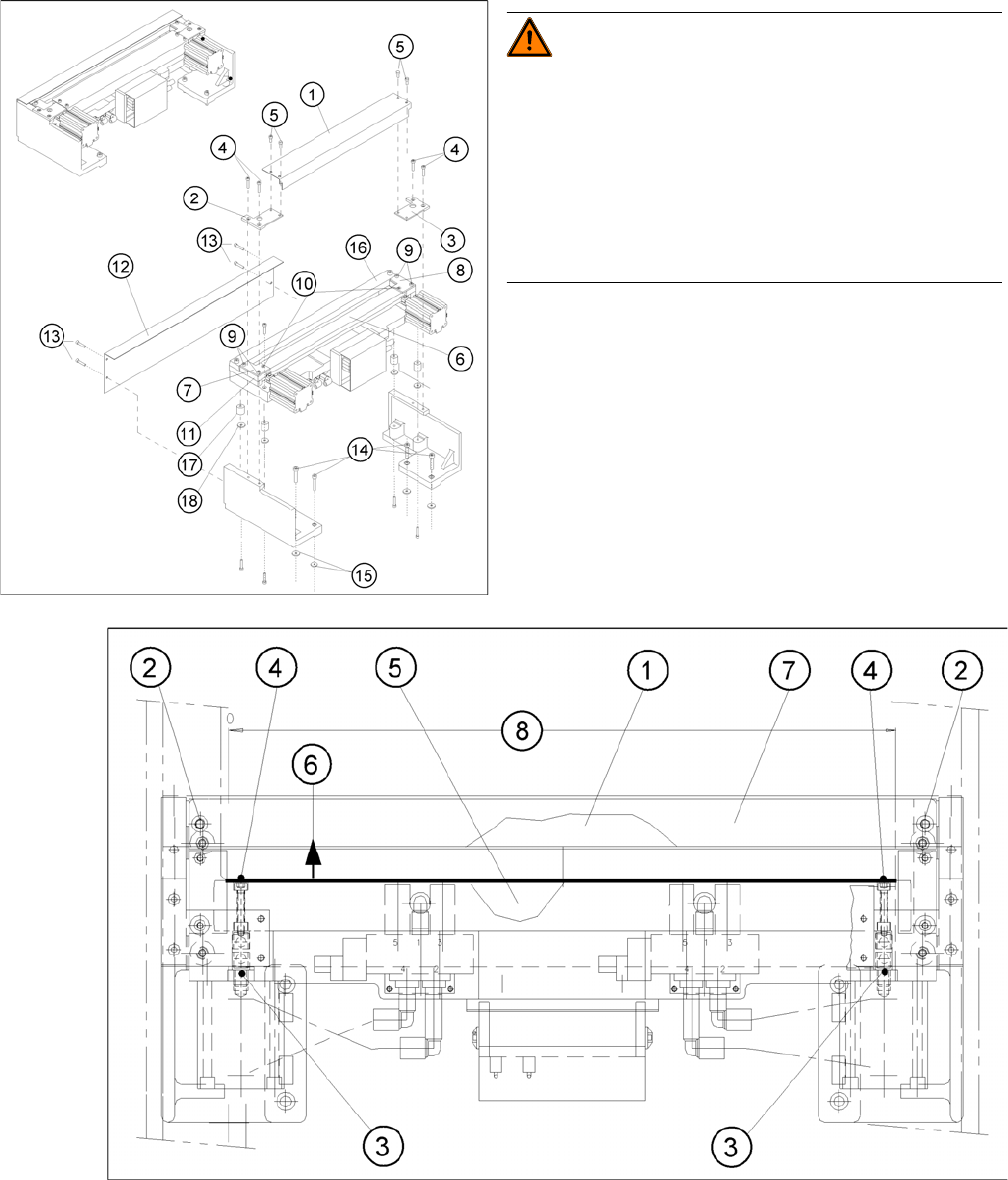
Removing the Blades
Removing/fitting the stationary and movable blade
WARNING! Risk of injury!
There is a high risk of injury from the blades and the tape
deflector.
Wear appropriately thick protective gloves!
Never reach into the cutter from below or into the empty-
tape duct from above.
Make sure that no-one can injure themselves on the cut-
ter, after it has been dismantled and placed next to the
machine!
► Remove the cutter.(See "4.3.2.5 Exchanging the
Pneumatic Cutter" [ ➙ 83].)
► Dismantle the deflector plate (12): 4 hexagon socket-
head screws M4 x 8 (13).

Service Work
4.3.2 Cutter Component Handling
Service Manual SIPLACE D4/D4i 89
Legend
► Loosen the screws fastening the stationary blade on the left and right (2).
► Mark the mounting position of the stationary blade (on the blade) with a water-insoluble marker (=
right end = right).
► Before any further disassembly, fasten the dismantled cutter to the retaining bracket (LH and RH)
with 2 parallel clamps, on a flat sturdy work bench, or screw it tight to the mounting plate with four
M6 hexagon socket head screws
► Remove the screw caps.
► Take hold of the stationary blade (1) by its ends and lift it up and out of the machine.
► Holding the articulated joint with a size 11 open-end wrench (3), loosen the screws fastening the ar-
ticulated joint in the movable blade (1 hexagon socket-head screw each on the right and left(4)).
► Push the movable blade in parallel (in the direction of the conveyor), until it is in the mounting position
of the stationary blade (for the direction of movement see (6)). Using a tool such as a screwdriver,
move the blade by alternately prying on the left and right next to the compressed air cylinder.
► Mark the mounting position of the movable blade (on the blade) with a water-insoluble marker (right
end = right).
► Lift the movable blade out of the cutter in this position.
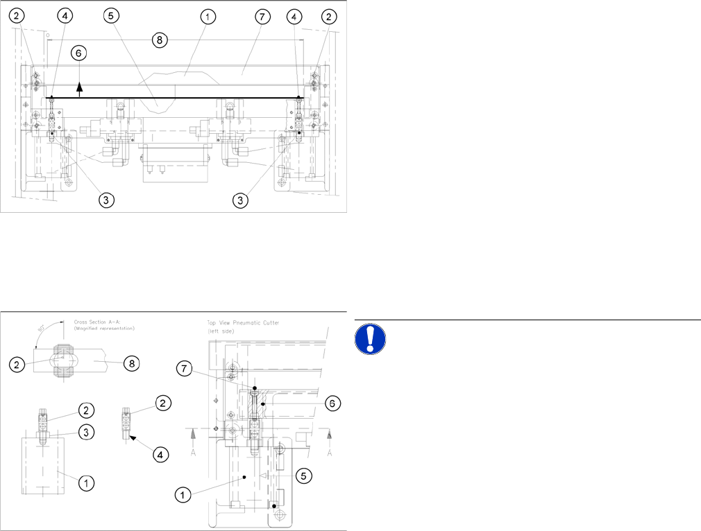
Installing the Blades
1 Stationary blade 5 Movable blade (under the tape deflector)
2 Fixture for the stationary blade (under the
deflector plate): 2 hexagon socket head
screws M6 x 35
6 Direction for removing the movable blade
3 Articulated joint 7 Deflector plate
4 Screws fastening the articulated joint in the
movable blade:
1 hexagon socket head screw M4 x 25 DIN
912 each; strength 12.9, Loctite No. 243
8 Cutter area
WARNING
Risk of injury!
► Wear appropriately thick protective gloves!
► There is a high risk of injury from the blades and the tape deflector.
CAUTION
Tighten the screws to the correct torque.
Make sure all parts are clean before installing them!
Do not use grease dissolving agents for cleaning!
Service Work
Component Handling 4.3.2 Cutter
90 Service Manual SIPLACE D4/D4i
► Afterwards, rotate the stationary blade 180° on its vertical axis to the original installation position, in-
sert it into the cutter in this position and screw it tight. The right-hand end of the blade must now be
on the left!
► Fit the stationary blade.
► Assemble the cutter in the reverse order to disassembly.(See "4.3.2.7 Replacing the Stationary
Blade and Movable Blade incl. Spacers" [ ➙ 91].)
► Remove the parallel clamps from the cutter or dismantle the cutter from the mounting plate.
► Fit the cutter back into the machine.(See "4.3.2.5 Exchanging the Pneumatic Cutter" [ ➙ 83].)
► Fit the empty-tape duct assembly and check the gap between the empty-tape baffle, inside and the
leading edge of the tape deflector.
► Perform the "Final Steps".
See also
4.3.2.4.1 Tightening Torques for Cutter Screws [ ➙ 83]
6.4.3 Check the gap between the empty-tape baffle, inside and the leading edge of the tape deflec-
tor. [ ➙ 223]
4.3.2.14 Final Steps [ ➙ 107]
► Wear appropriately thick protective gloves!
► Make sure that the blades (1, 5) are clean. If they are
not, wipe all of their surfaces very carefully with a
clean cloth which has been folded several times.
► Turn the movable blade 180 ° on its vertical axis to
the previously marked installation position:
► Insert the movable blade into the cutter, in this angle
of rotation and push it in parallel, back into the original
mounting position.
► Apply Loctite no. 243 to the two M4 screws (4), to fas-
ten the joint in the moveable blade.
► Reinsert these screws in the left and right of the mov-
able blade.
► Align the articulated joint (3) so that the slanted side
of the blade engages with the slot in the blade.
NOTICE! Make certain that the midline / open-
end wrench surface of the articulated joint (2) is at right
angles to the slide surface of the movable blade (5, 6), so
that the articulated joint can slide smoothly in the slot (=
prevents turning) of the movable blade (8) .
► Use the size 11 open-end wrench to hold the appro-
priate articulated joint (2) and tighten the two screws
(7) .