SIPLACE D4-D4i 工程师手册_EN.pdf - 第95页
Service Work 4.3.2 Cutter Component Handling Service Manual SIPLACE D4/D4i 95 See also 4.3.2.7 Replacing the Stationary Blade and Movable Blade incl. Spacer s [ ➙ 91] 4.3.2.4.1 Tighte ning Torques for Cutter Scre…
Service Work
Component Handling 4.3.2 Cutter
94 Service Manual SIPLACE D4/D4i
► Using the feeler gauge, check the gap between tape deflector and movable blade, over the entire
length and width of the blade:
⇨ The 0.05 mm feeler gauge should fit through the gap.
⇨ The 0.25 mm feeler gauge should not fit through the gap.
If the gap is not correct, check:
► Whether the wrong holddowns has been installed (with function status < 03).
The holddowns are those designed for cutters with function status -04 (= with tape deflector).
► Whether the blades, tape deflector etc. were cleaned before installation
If the gap is correct:
► Carefully fold the cover plate (with cover plate holders installed) back over the tape deflector.
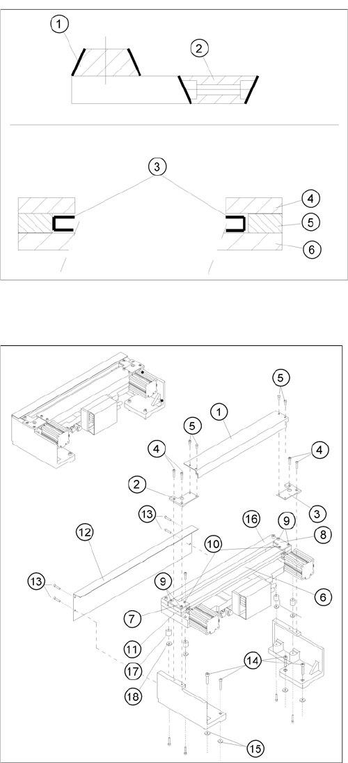
Mounting new blades, mounting position of the blades,
slide surfaces to be greased
► Grease the contact / slide surfaces for the movable
blade exactly in the area shown (3).
⇨ Do not lubricate the blades themselves.
► Place an adjustment plate (0.5 to 1.0 mm thick) on
the left and right, between the spacer and the face of
the movable blade.
► Place the holddowns previously removed back on the
new spacers.
⇨ The version 03 holddowns match the version 04
cutters (= with tape deflector)!
► Reinstall the previously removed deflector holder (=
with tape deflector) and initially tighten the 4 hexagon
socket head screws (9) hand-tight.
► Push the spacers (with inserted adjustment plate) to-
wards the movable blade - up to the stop but not until
they exert pressure against it, otherwise it would no
longer be possible to remove the adjustment plates.
⇨ The maximum permissible gap is 1.0 mm.
► In this position, tighten all 4 screws on the tape de-
flector holders crosswise.
⇨ Tighten the screws to the correct torque.
► Remove the two shim rings.
► Insert the new stationary blade in the correct position
((see diagram) and screw tight (2 screws).
⇨ Tighten the screws to the correct torque.
Service Work
4.3.2 Cutter Component Handling
Service Manual SIPLACE D4/D4i 95
See also
4.3.2.7 Replacing the Stationary Blade and Movable Blade incl. Spacers [ ➙ 91]
4.3.2.4.1 Tightening Torques for Cutter Screws [ ➙ 83]
6.4.3 Check the gap between the empty-tape baffle, inside and the leading edge of the tape deflec-
tor. [ ➙ 223]
4.3.2.14 Final Steps [ ➙ 107]
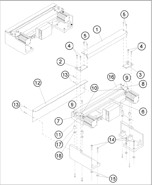
► Make certain that the edges are parallel, then screw
the cover plate holder to the cutter (two M4 screws
each (7, 9)):
⇨ -> Do not pinch or put strain on the cables.
► Install the cover plate on the stationary blade (4 M4
screws (12, 13)).
► Remove the parallel clamps from the cutter or dis-
mantle the cutter from the mounting plate.
► Fit the cutter back into the machine. (See "4.3.2.5 Ex-
changing the Pneumatic Cutter" [ ➙ 83].)
► Fit the empty-tape duct assembly and check the gap
between the empty-tape baffle, inside and the leading
edge of the tape deflector.
► Perform the appropriate “Final Steps”.
Service Work
Component Handling 4.3.2 Cutter
96 Service Manual SIPLACE D4/D4i
4.3.2.8
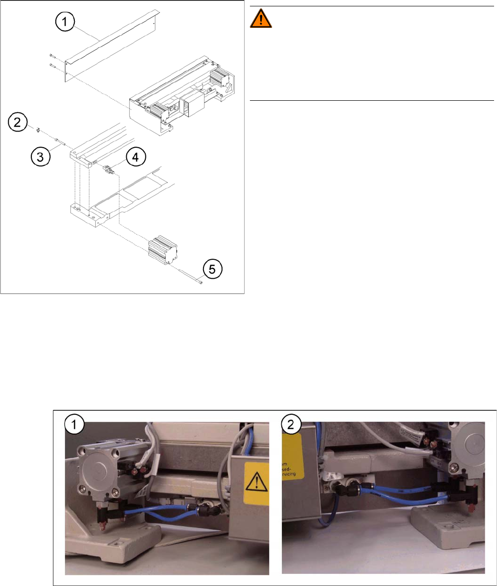
4.3.2.8 Replacing the Articulated Joint on the Short-Stroke Cylinder [00348579-xx]
Replacing the Articulated Joint on the Short-Stroke Cylinder [00348579-xx]
Removing the articulated joint and short-stroke cylinder
► Remove the cutter from the machine. (See "4.3.2.5 Exchanging the Pneumatic Cutter" [ ➙ 83].)
► Remove the deflector plate from the cutter.
► Loosen the screws holding the moveable blade.
Compressed air connections, left (1) and right (2)
► Loosen the compressed air connections (1, 2) on the short-stroke cylinder.
► In addition, mark the allocation of the proximity switches to the short-stroke cylinder (position front/
back).
Replacing the articulated joint on the short-stroke cylin
-
der
WARNING! Risk of injury!
Wear appropriately thick protective gloves!
There is a high risk of injury from the blades and the tape
deflector.
Never reach into the cutter from below or into the empty-
tape duct from above.
Legend
1. Deflector plate
2. Cover
3. Screws to fasten short-stroke cylinder
4. Articulated joint
5. Screws to fasten the moveable blade