SIPLACE D4-D4i 工程师手册_EN.pdf - 第97页
Service Work 4.3.2 Cutter Component Handling Service Manual SIPLACE D4/D4i 97 Removing and Insta lling the Short-Stroke Cylinder Legend ► Loosen the screws fastening the tw o inductive proximity switche s to the short-st…
Service Work
Component Handling 4.3.2 Cutter
96 Service Manual SIPLACE D4/D4i
4.3.2.8
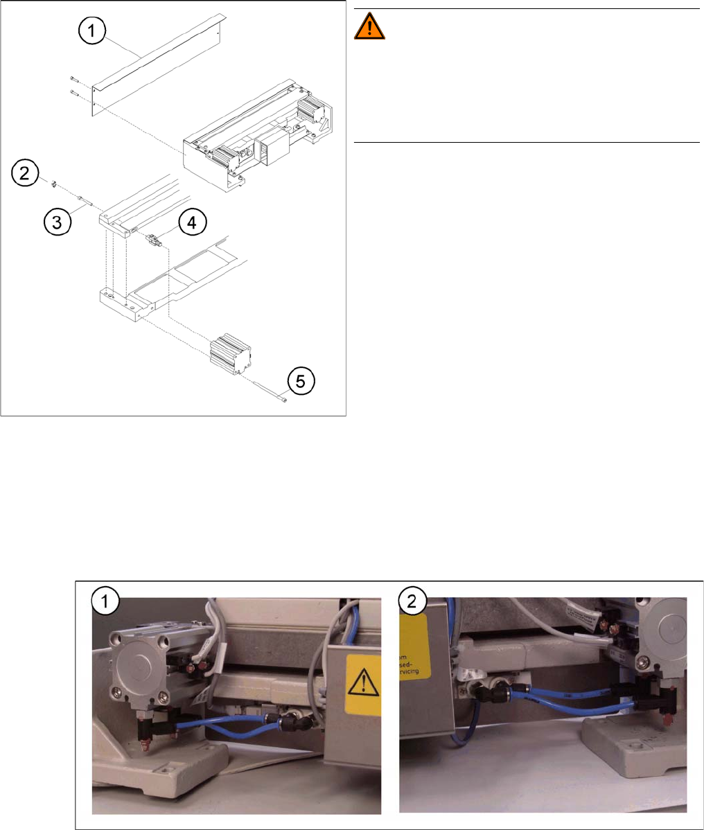
4.3.2.8 Replacing the Articulated Joint on the Short-Stroke Cylinder [00348579-xx]
Replacing the Articulated Joint on the Short-Stroke Cylinder [00348579-xx]
Removing the articulated joint and short-stroke cylinder
► Remove the cutter from the machine. (See "4.3.2.5 Exchanging the Pneumatic Cutter" [ ➙ 83].)
► Remove the deflector plate from the cutter.
► Loosen the screws holding the moveable blade.
Compressed air connections, left (1) and right (2)
► Loosen the compressed air connections (1, 2) on the short-stroke cylinder.
► In addition, mark the allocation of the proximity switches to the short-stroke cylinder (position front/
back).
Replacing the articulated joint on the short-stroke cylin
-
der
WARNING! Risk of injury!
Wear appropriately thick protective gloves!
There is a high risk of injury from the blades and the tape
deflector.
Never reach into the cutter from below or into the empty-
tape duct from above.
Legend
1. Deflector plate
2. Cover
3. Screws to fasten short-stroke cylinder
4. Articulated joint
5. Screws to fasten the moveable blade
Service Work
4.3.2 Cutter Component Handling
Service Manual SIPLACE D4/D4i 97
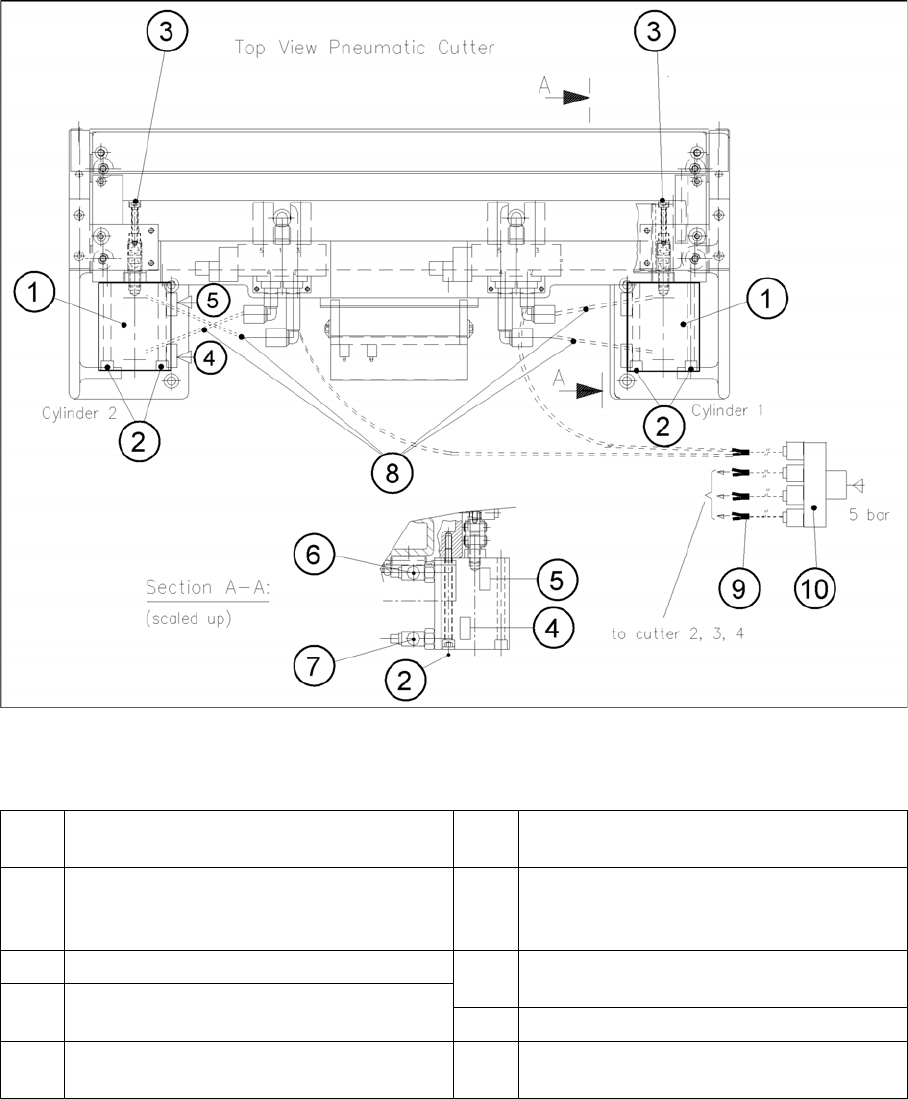
Removing and Installing the Short-Stroke Cylinder
Legend
► Loosen the screws fastening the two inductive proximity switches to the short-stroke cylinder (1
screw each (4, 5)).
► Loosen the screws fastening the short-stroke cylinder (1) (2 M5x65 screws (5)) and remove the cyl-
inder, incl. the articulated joint screwed into it.
1 Short-stroke cylinders 1 and 2 6 One-way restrictor (for running cylinder
out)
2 Screws fastening the short-stroke cylin-
ders: 2 M 5x65 hexagon socket-head
screws each
7 One-way restrictor (for running cylinder in)
3 Articulated joint fixtures 8 Allocation of the compressed air connec-
tions, pneumatic hoses
4 Proximity switch (for position cylinder
moved in). Fastener: 1 Phillips screw 9 Y-socket union (in the cable duct)
5 Proximity switch (for position cylinder
moved out). Fastener: 1 Phillips screw
10 Multiple-Y-distributor on the safety valve (5
bar from compressed air unit)
Service Work
Component Handling 4.3.2 Cutter
98 Service Manual SIPLACE D4/D4i
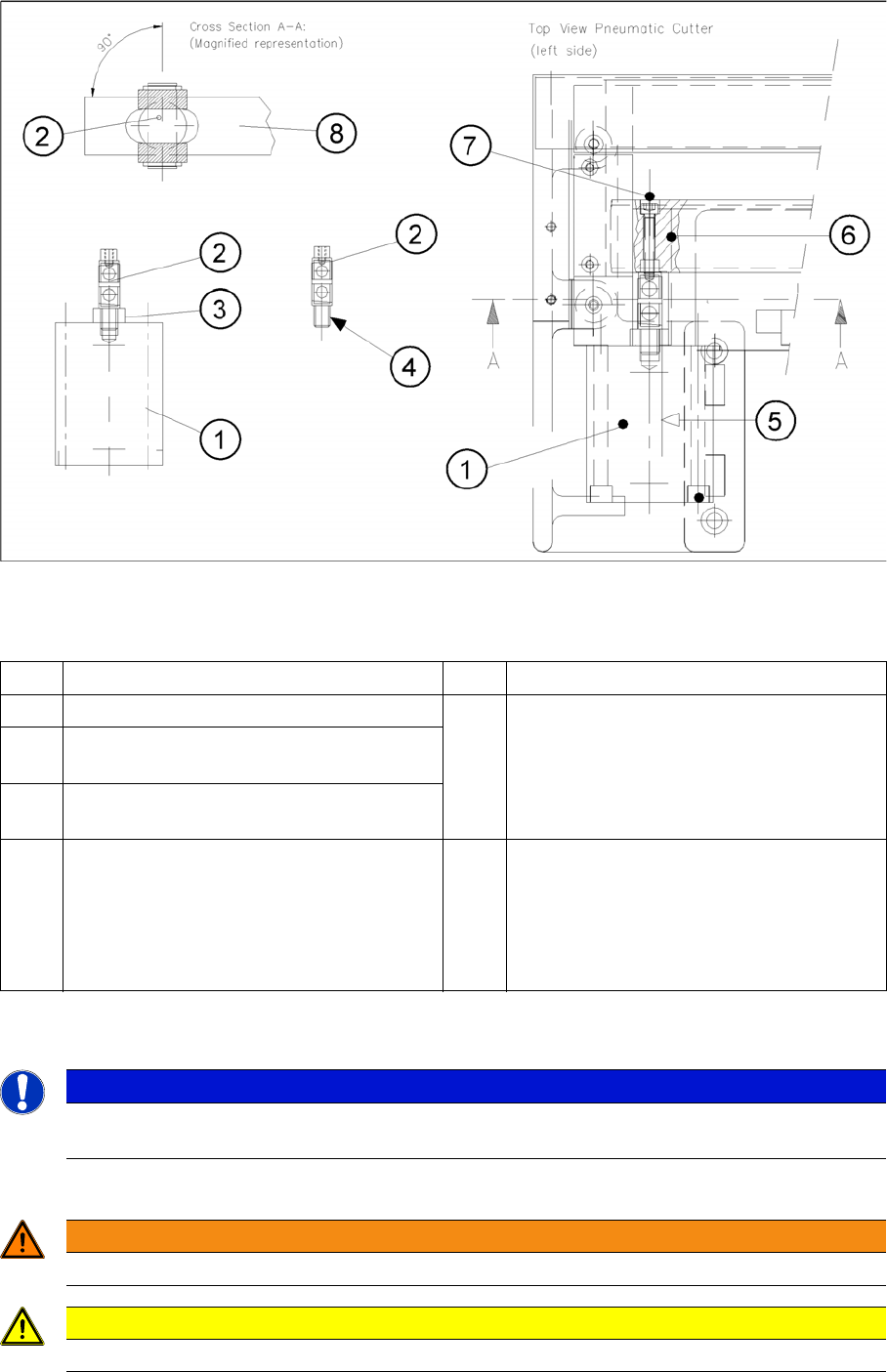
Removing Articulated Joint, Installing It on New Master Cylinder and Bonding It in Place
Legend
► Dismantle the articulated joint (2) from the cylinder (1) by turning the open-end wrenches
(SW 11, 14) on the surfaces marked (3) .
Installing the articulated joint and short-stroke cylinder
► Apply a small amount of Loctite no. 243 to the thread of the new joint.
1 Short-stroke cylinder (1 or 2) 6 Slide surface of the movable blade
2 Articulated joint (complete) 7 Screw fastening the articulated joint to the
movable blade:
One M4 x 24 DIN 912 socket hex head cap
screw each, strength 12.9, secured with
Loctite no. 243
3 Wrench surface for disassembling the artic-
ulated joint
4 Secure articulated joint thread with Loctite
no. 243
5 Open-end wrench surface of articulated
joint
8 Movable blade with slot to prevent the artic-
ulated joint from turning if the articulated
joint is damaged, use a (complete) new one
(article no.: see ) or clean the residues of
Loctite from the thread of the existing artic-
ulated joint pin.
NOTICE
The threaded pin is secured with Loctite no. You will need somewhat more strength than usual
to loosen it.
WARNING
There is a high risk of injury from the blades and the tape deflector!
CAUTION
Tighten the screws to the correct torque.