SIPLACE D4-D4i 工程师手册_EN.pdf - 第99页
Service Work 4.3.2 Cutter Component Handling Service Manual SIPLACE D4/D4i 99 ► If the enamel on the one-wa y restricto r is damage d use a new "s hort-stroke cylinder". DANGER One-way restrictors may not be s …
Service Work
Component Handling 4.3.2 Cutter
98 Service Manual SIPLACE D4/D4i
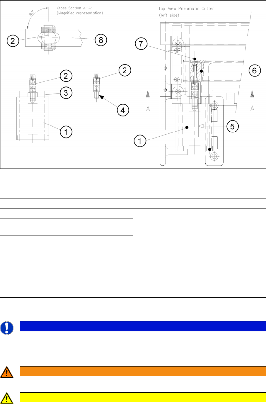
Removing Articulated Joint, Installing It on New Master Cylinder and Bonding It in Place
Legend
► Dismantle the articulated joint (2) from the cylinder (1) by turning the open-end wrenches
(SW 11, 14) on the surfaces marked (3) .
Installing the articulated joint and short-stroke cylinder
► Apply a small amount of Loctite no. 243 to the thread of the new joint.
1 Short-stroke cylinder (1 or 2) 6 Slide surface of the movable blade
2 Articulated joint (complete) 7 Screw fastening the articulated joint to the
movable blade:
One M4 x 24 DIN 912 socket hex head cap
screw each, strength 12.9, secured with
Loctite no. 243
3 Wrench surface for disassembling the artic-
ulated joint
4 Secure articulated joint thread with Loctite
no. 243
5 Open-end wrench surface of articulated
joint
8 Movable blade with slot to prevent the artic-
ulated joint from turning if the articulated
joint is damaged, use a (complete) new one
(article no.: see ) or clean the residues of
Loctite from the thread of the existing artic-
ulated joint pin.
NOTICE
The threaded pin is secured with Loctite no. You will need somewhat more strength than usual
to loosen it.
WARNING
There is a high risk of injury from the blades and the tape deflector!
CAUTION
Tighten the screws to the correct torque.
Service Work
4.3.2 Cutter Component Handling
Service Manual SIPLACE D4/D4i 99
► If the enamel on the one-way restrictor is damaged use a new "short-stroke cylinder".
DANGER
One-way restrictors may not be set at the machine. This is only permitted at the factory.
For this reason the replacement short-stroke cylinder must always be installed, together with
the new, already adjusted restrictors attached to it.
Removing Articulated Joint, Installing It on New Master
Cylinder and Bonding It in Place
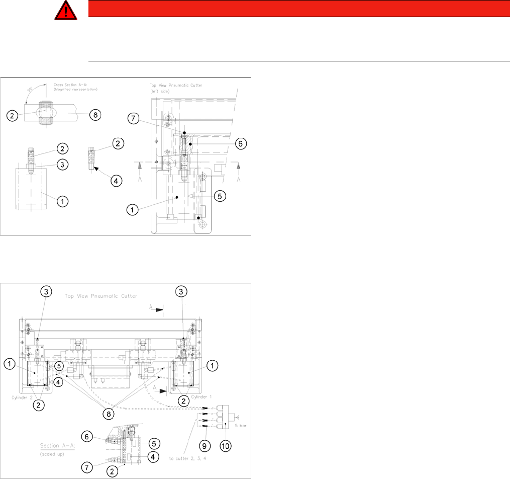
► Screw the articulated joint into the short-stroke cylin-
der.
► Turn the articulated joint into the installation position.
Once the cylinder is installed, the slot in the moveable
blade prevents the articulated joint from turning.
► Copy the exact mounting position of the proximity
switch to the short-stroke cylinder (feeler gauge, fine-
tip marker).
► Install the prepared cylinder - complete with one-way
restrictors - on the cutter, in the correct rotational po-
sition for the articulated joint.
► Fasten the cylinder in this position, with the 2 M5x65
screws (2) provided.
► Install the proximity switch (Item No. see section 5.2)
precisely in the position you marked on the short-
stroke cylinder with the permanent marker (4, 5).
► Connect the compressed air hoses to the one-way re-
strictor on the cylinder, in the correct allocation (see
markings).
⇨ One-way restrictor (for running cylinder out) (6)
⇨ One-way restrictor (for running cylinder in) (7)
⇨ Allocation of the compressed air connections,
pneumatic hoses (8)
Service Work
Component Handling 4.3.2 Cutter
100 Service Manual SIPLACE D4/D4i
See also
4.3.2.4.1 Tightening Torques for Cutter Screws [ ➙ 83]
6.4.3 Check the gap between the empty-tape baffle, inside and the leading edge of the tape deflec-
tor. [ ➙ 223]
4.3.2.14 Final Steps [ ➙ 107]
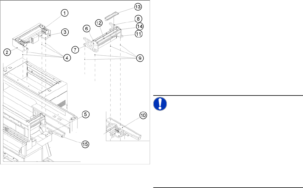
► Perform the following steps as described in "4.3.2.7
Replacing the Stationary Blade and Movable Blade
incl. Spacers" [ ➙ 91]:
⇨ Fasten the moveable blade to the articulated joint.
► Fit the empty-tape duct (6) on the machine base (2
screws each on the left and right (9)).
► Check the gap between the empty-tape baffle, inside
and the leading edge of the tape deflector.
► Check the switching points of the proximity switches.
(See "4.3.2.11 Exchanging the Inductive Proximity
Switch" [ ➙ 104].)
NOTICE! If the tapes are not cut correctly, even
though the switching points are set properly and the
short-stroke cylinder has been exchanged, complete with
the one-way restrictor, the cause of the problem may be:
Incorrect compressed air value/leaky pneumatic connec-
tion
Y socket union
Blade in poor condition
Faulty solenoid valve or
Interruption of solenoid valve activation
► Perform the appropriate “Final Steps”.