DECAN_S1_Troubleshooting_Guide(Eng_Ver1.3)_Print_Web.pdf - 第198页
1-174 Next Generation, Multi-Functional Plac er DECAN S1 Troubleshooting Guide SACO-related abnormal signal (normal input) Reconnect the SACO board CN18. Check whether the READY SW operates properly . Reconnect the…
1-173
System Messages of the MMI and Solutions
$e211 PLC Monitoring I/O error. Please check door is firmly closed, follow PLC monitoring
io check procedure. [EMER LEVEL]
[Problem]
The PLC is defective.
[Solution]
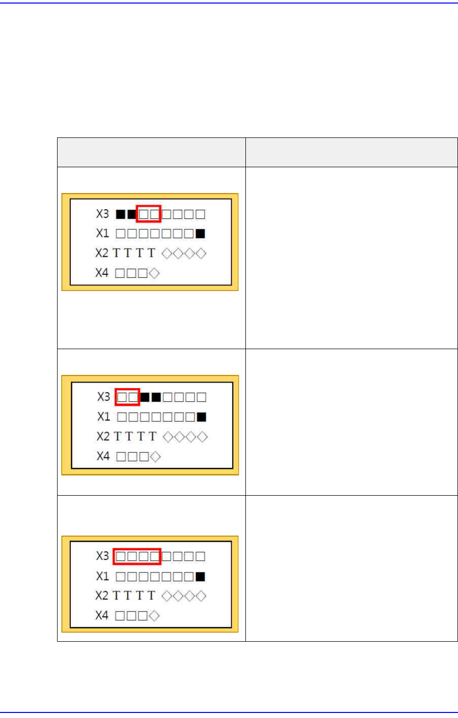
Checking the DISPLAY window (How to handle by error status)
Error status How to handle
Door Open Status Open and then close the door
(front / rear).
Push the closed door firmly.
(Front/rear)
Check with MMI whether the Door
Switch operates normally.
Reconnect the T2, T3, IM2, and
IM3 terminals.
If the problem cannot be solved,
check the Error message.
Emergency Switch operation status Confirm that the EMG SW is off.
(Front/rear)
Using MMI, check whether the
EMG SW operates normally.
Reconnect terminals T0, T1, IM0,
and IM1.
If the problem cannot be solved,
check the Error message.
Door Open & EMG Switch operation
status
Check how to handle the “Door
Open status”.
Check how to handle the “EMG
Switch operation status”.
If the problem cannot be solved,
check the Error message.
1-174
Next Generation, Multi-Functional Placer DECAN S1 Troubleshooting Guide
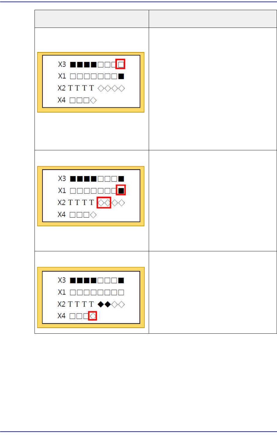
SACO-related abnormal signal
(normal input)
Reconnect the SACO board
CN18.
Check whether the READY SW
operates properly.
Reconnect the SACO board CN3
and CN30. (F-OP)
Reconnect the SACO board CN4
and CN31. (R-OP)
Reconnect the PLC I7 terminal.
If the problem cannot be solved,
check the Error message.
Abnormal MC signal (normal input) Reconnect the PLC o0, o1, and
I15 terminals.
Reconnect the TB-21D terminal.
Check the MC terminal
connection.
Check if the NC (Not Connected)
terminal is connected.
If the problem cannot be solved,
check the Error message.
Abnormal PLC Check whether the DOOR and
EMG SW operate normally.
Check whether the SACO signal
operates normally.
Check whether the MC signal
operates normally.
If all is normal, replace the PLC.
Error status How to handle
1-175
System Messages of the MMI and Solutions
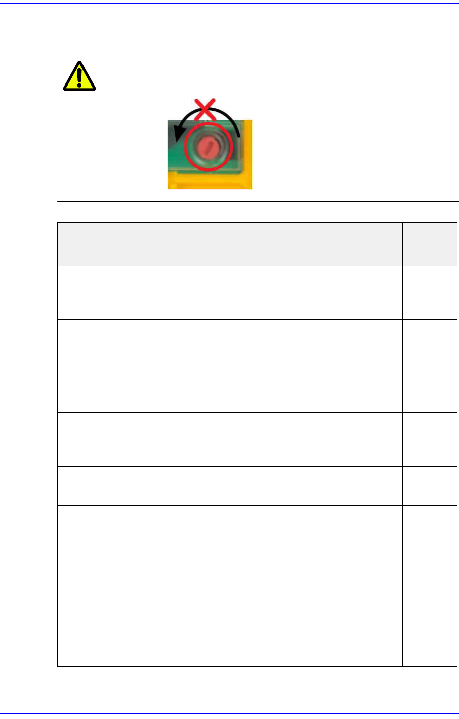
Checking the Error message in the Display window. (Check the Error Message by
pressing the Rotary Knob.)
Caution Do not rotate the Rotary Knob.
Error Messages Error Solution
Terminal
s
FAULTY PROJECT There is a mismatch
between the program and
physical hardware.
Check the chip
card assembly.
CHIP CARD ? Cannot read the chip card. Check the chip
card assembly.
FAULTY DEVICE Module error. Check and
replace the safety
PLC module.
PARTIALLY
OPERATED
Single operation of the
redundant input sensor.
Check the Door
and EMG
connection.
T0~T3,
IM0~3
FEED BACK LOOP Feedback error from MC
that is connected to output.
Check the wiring. I15
FAULTY OUTPUT Output stage signal error. Check the MC
wiring.
o0,o1
LOAD SUPPLY Output power error. Check the power
supply, and check
the wiring.
A1,A2,0V
,24V
SUPPLY LOW/
HIGH
The supply power is lower /
higher than the allowable
value.
Check the wiring,
and check the
power of Power
Supply.
A1,A2,0V
,24V