SMN-Tape Feeder Manual(Eng Ver5).pdf - 第35页
Operation of the T ape Feeder 2-5 Figur e 2-8. Installing the upper cover tape of the tape feeder Pass the carrier tape through groove B. Figur e 2-9. Exit of the carrier tape of t he 8mm tape feeder U pp er cover ta p e…
Samsung SM-Series Pneumatic Tape Feeder Users' Manual
2-4
2.1.3. Installing the component tape and Exit of the carrier tape
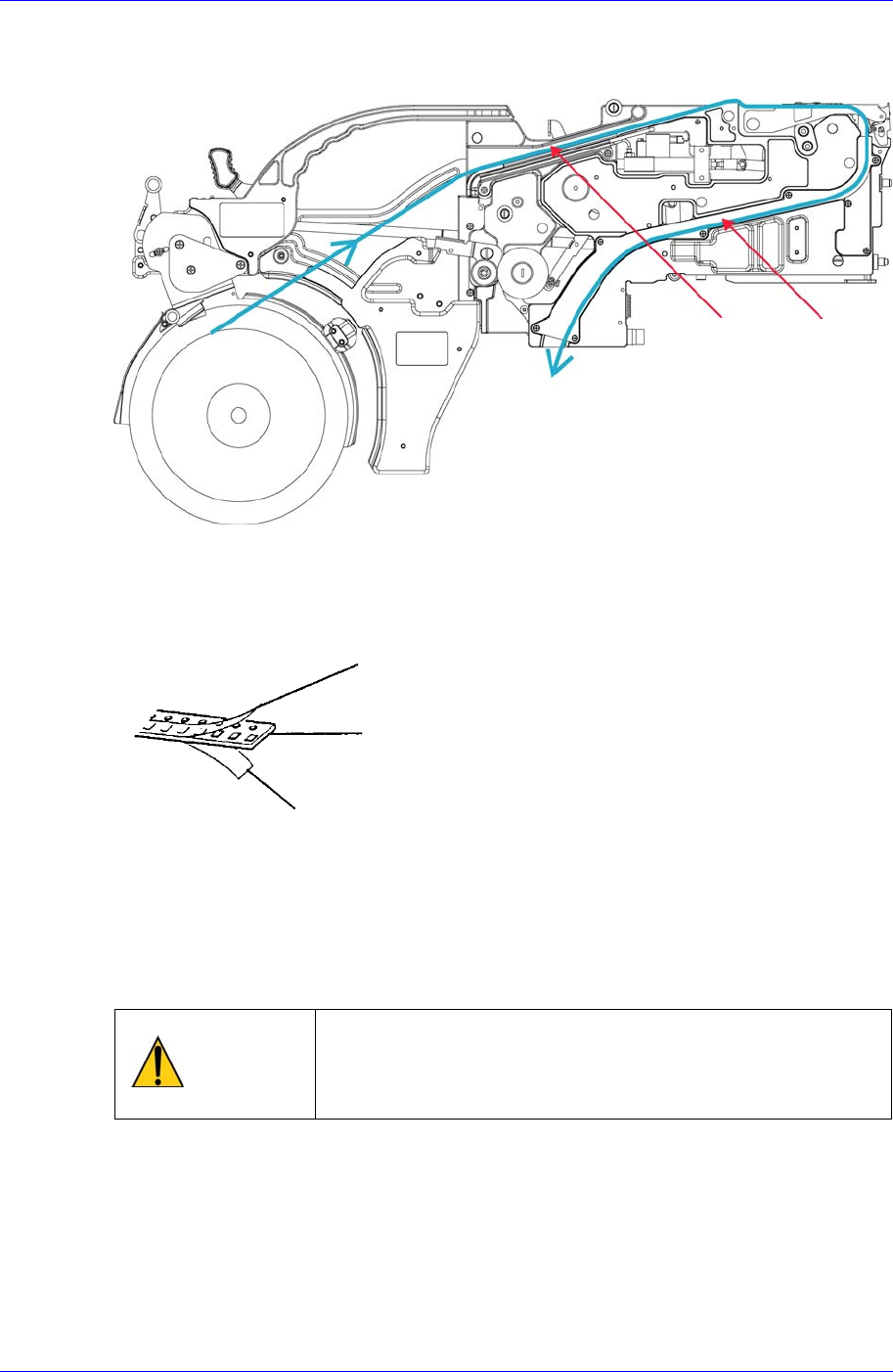
Pass the tape through groove A as shown in the figure below.
Figure 2-6. Installing path of the tape
The tape consists of three parts, the upper cover tape, the carrier tape, and the bottom
cover tape. In general, the carrier tape and the upper cover tape are not separated, so
together they are called the carrier tape.
Figure 2-7. Composition of the tape
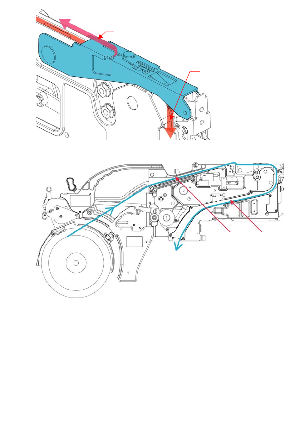
After passing the upper tape and transportation tape between the tape guide slot and main
frame as shown in the figure, strip off about 35cm of the upper cover tape from the end,
Strip off about 35cm of the upper cover tape from the end, and pass it through the tape slit
as shown in the figure below.
Caution
When the distance from the end of the feeding tape to the
pickup position is short, the tape may get caught.
Therefore, ensure that the distance is sufficiently long
before use.
상단 커버 테이프
전송 테이프
하단 커버 테이프
Carrier tape
Bottom cover tape
Upper cover tape
Groove A
Groove B
Operation of the Tape Feeder
2-5
Figure 2-8. Installing the upper cover tape of the tape feeder
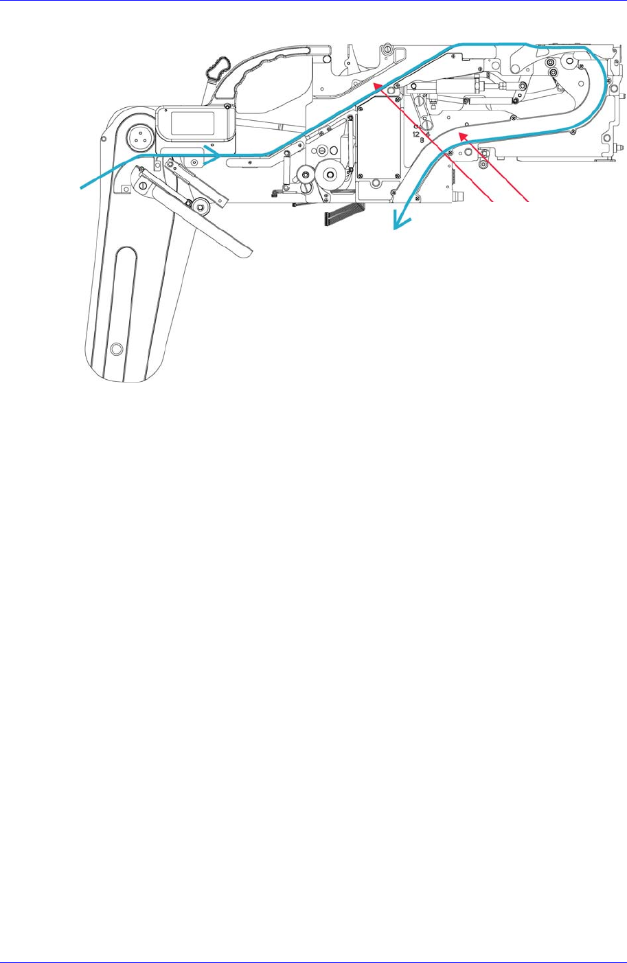
Pass the carrier tape through groove B.
Figure 2-9. Exit of the carrier tape of the 8mm tape feeder
U
pp
er cover ta
p
e
Carrier tape
Groove A
Groove B
Samsung SM-Series Pneumatic Tape Feeder Users' Manual
2-6
Figure 2-10. Exit of the carrier tape of the 12-88mm tape feeder
Groove A
Groove B